


Electrical Transformers
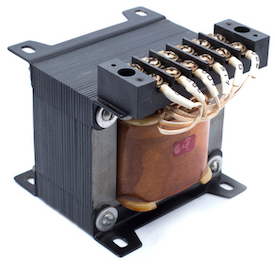
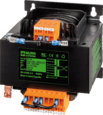
Figure 1: Transformer
A transformer is an electromagnetic device that transfers electrical energy between circuits without altering frequency or power. It improves the efficiency and safety of power systems by adjusting voltage levels as required. A transformer operates only with alternating current (AC) input, but when combined with semiconductor components, it can generate direct current (DC) output. This article covers the main transformer types, wiring methods, and applications.
Table of contents
- Transformer working principle
- Transformer construction
- Electrical transformer types
- Transformer wiring and symbol
- DC transformers
- Isolation transformer
- Transformer applications
View our online selection of transformers!
Transformer working principle
A transformer works on the principle of electromagnetic induction, which states that a current-carrying conductor produces a magnetic field around it and vice-versa. A transformer consists of two sets of wires (see Figure 2):
- Primary winding (A): collects power
- Secondary winding (B): provides power
The primary and secondary windings are wound together on a magnetic iron circuit core, but these coils are not in contact with one another, as seen in Figure 2. The core is made of a soft magnetic material consisting of laminations (Figure 2 labeled B) linked together to help reduce core loss. Core loss is the energy loss within the core caused by an alternating magnetic flux. An unstable magnetic field eventually destroys the core material's functioning.
When the primary winding (Figure 2 labeled A) is connected to an alternating power supply, current flows through the coil, and a magnetic flux is induced. A part of this magnetic field links with the secondary windings (Figure 2 labeled C) by mutual induction, thereby producing a current flow and voltage at the secondary (load) side. The voltage produced at the load side is proportional to the number of turns in the secondary winding relative to that in the primary side. The voltage and current transformation are given by:
V1 / V2 = N1 / N2 = I2 / I1
- V1: Voltage applied to the transformer primary winding
- V2: Voltage produced at the secondary (load) winding of the transformer
- N1: Number of turns in the primary winding
- N2: Number of turns in the secondary winding
- I1:Current in the primary winding
- I2:Current through the secondary winding
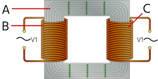
Figure 2: Primary windings (A), magnetic core(B), and secondary windings (C) of a transformer
Transformer construction
Depending on how the primary and secondary windings are wound around the central laminated steel or iron core, there are two basic designs of transformer construction:
- Core type transformer: In a core-type transformer, the primary and secondary coils are wound outside and surround the core ring, as seen in Figure 3.
- Shell type transformer: In a shell-type transformer, the primary and secondary windings pass inside the magnetic steel core, forming a shell around the windings, as seen in Figure 4.
Read our article on single-phase transformers for the complete list of transformer parts and their functions.
Transformer core construction
Core type transformers
In the core type transformer construction, one-half of the winding is wrapped around each leg (or limb) of the transformer’s magnetic circuit (Figure 3 labeled B). Half of the secondary winding and half of the primary winding are placed one over the other concentrically on each leg. This facilitates an increased magnetic coupling between the windings (Figure 3 labeled A). This allows practically all magnetic lines of force to pass both the primary and secondary windings simultaneously. However, with this type of transformer construction, a small percentage of the magnetic lines of force flow outside of the core (known as leakage flux).
The cylindrical coils have different layers, and each layer is insulated from the other. Materials like paper, cloth, or mica are commonly used for insulation. Low voltage windings are placed adjacent to the core, as they are easier to insulate.
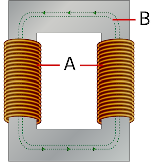
Figure 3: Core-type transformer: windings (A) and magnetic part (B)
Shell type transformers
In a shell-type transformer, the primary and secondary coils are wound and mounted in layers stacked with insulation between them (Figure 4 labeled A). Both the primary and secondary windings are wound on the same center limb or leg, which has twice the cross-sectional area of the two outer limbs. A proper insulating medium separates both the windings. As primary and secondary coils are wound close together, a shell-type transformer has the advantage of decreasing core losses and increasing overall efficiency.
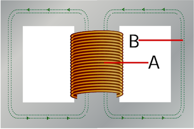
Figure 4: Shell-type transformer with layers of primary and secondary windings (A) and core (B)
Transformer laminations
The laminations used in transformer construction are thin strips of insulated metal joined together to produce a solid but laminated core. Having one big solid iron core as the magnetic core material of the transformer gives rise to core issues like eddy current losses. Hence, splitting the magnetic path into many thin pressed steel shapes called laminations is essential.
The primary and secondary coils are first wound on a coil former having a rectangular, cylindrical, or oval cross-section that suits the construction of the laminated core. The coil former determines the working space, connection paths, and the direction of heat flow. The individual laminations are stamped out from larger steel sheets and formed into thin steel strips resembling the letters ‘L, ‘E’, ‘U’, and ‘I’ as seen in Figure 6.
Transformer core types
The lamination stampings, when connected together, form the required core shape. For example, ‘E’ stampings plus an end closing ‘E’ stampings give an E-E core, forming one element of a standard shell-type transformer core as seen in Figure 5. The individual laminations are tightly butted together during the construction phase to reduce air gap reluctance at the joints, thereby producing a highly saturated magnetic flux density.
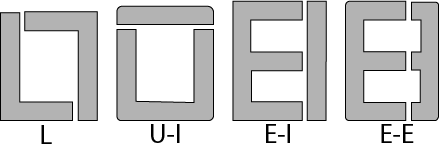
Figure 5: Transformer core types
Electrical transformer types
Core-type transformer and shell-type transformer
Based on construction, transformers are classified into core-type transformers and shell-type transformers.
Step-up transformer and step-down transformer
Based on their purpose, transformers are classified into step-up transformers and step-down transformers.
- A step-up transformer increases the voltage at the secondary windings with respect to that on the primary side (with a subsequent decrease in current).
- A step-down transformer decreases the voltage at the secondary windings with respect to that on the primary side (with a subsequent increase in current).
Single-phase transformer and three-phase transformer
Based on power supply, transformers are classified into single-phase transformers and three-phase transformers. Single-phase transformers work on a single-phase power supply, whereas a three-phase transformer works on a three-phase power supply.
Power transformer, distribution transformer, and instrumentation transformer
Based on their use, transformers are classified into:
- Power transformer: A power transformer is a conventional high-rating transformer used in transmission networks.
- Distribution transformer: A distribution transformer or service transformer is a transformer that provides the final voltage transformation in the electric power distribution system. These transformers step down the voltage used in distribution lines to the level used by the customer.
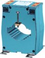
- Instrumentation transformer: Instrument transformers provide insulation and protection in relays and commercial metering devices. These transformers also measure a very high voltage that cannot be measured by a conventional voltmeter. There are two types of instrument transformers, namely current transformer, and voltage transformer.
Transformer wiring and symbol
Transformer wiring diagrams are usually printed on the transformer nameplate, traditionally affixed to the transformer case surface or printed inside the cover to the wiring compartments. The lead wires are marked ‘H’ (primary leads) and ‘X’ (secondary leads). The H windings are connected to the power supply and the X windings to the load, as seen in Figure 6.
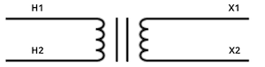
Figure 6: Transformer symbol
Some transformers have two windings, each in the primary and secondary windings. These transformers are called dual voltage transformers, and the multiple windings allow flexibility in creating several voltages for different applications.
Consider a dual voltage transformer rated at 240/480V on the primary side and 120/240V on the secondary side. Each of the two primary windings is rated at 240V. Each of the two secondary windings is rated at 120 V. The 240/480V primary side rating means that each of the 240V combinations can be utilized to give a net primary side voltage of 240V or 480V. Similarly, the 120/240V primary side rating means that each of the 120V combinations can be utilized to give a net secondary side voltage of 120V or 240V.
To design a 480V to 240V(480 V on the primary side and 240V on the secondary side) transformer, the primary windings are connected in series, with H1 and H4 connected to a 480V power supply. The voltage across HI and H2 is 240 V, and that across H3 and H4 is 240 V. Hence connecting them in series gives a net primary voltage of 480V. With each primary winding receiving the proper 240V, each secondary windings receives 120V. Connecting the secondary windings in series produces 240V across X1 and X4, as shown in Figure 7.
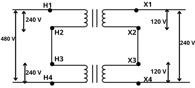
Figure 7: Creating series connections in primary and secondary windings of a transformer
If needed, the primary side can also be connected to a 240 V supply. For this, connect either H1 and H3 or H2 and H4 to a 240V power supply. To design a 480V to 120V transformer (480V on the primary side and 120 V on the secondary side), the primary windings are connected in series, with H1 and H4 connected to a 480V supply. The secondary windings are connected in parallel (X1 to X3 and X2 to X4), as seen in Figure 8.
Note: Connecting the windings in parallel should be done with proper caution to prevent a dead short that will ruin the transformer when energized. Use a voltmeter to make sure the connection is correct. Connect X1 to X3, and then connect a voltmeter between X2 and X4. Energize the primary and read the voltmeter. If the connection is correct, the voltmeter will read zero. If the voltmeter reads something other than zero, check all primary and secondary connections to make sure they are connected exactly as indicated by the manufacturer.
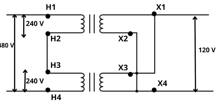
Figure 8: Series connection across the primary windings and parallel connection across the secondary windings of the transformer
AC to DC transformers
A transformer is a static device that works on the principle of mutual induction. An AC voltage should be applied to the primary windings of the transformer to create an alternating magnetic flux at the primary side that links with the secondary windings to create a proportional load voltage. A DC voltage doesn’t produce an alternating magnetic field or flux; hence a transformer doesn’t work with DC input power. However, the alternating output voltage can be converted into a corresponding DC voltage by adding appropriate semiconductor components like diode and capacitor at the transformer output.
A rectifier is a circuit that converts alternating current (AC) to direct current (DC). A half-wave rectifier or a full-wave rectifier can be used to convert an alternating voltage to DC voltage. An alternating voltage (Figure 9 labeled A) is applied to the primary windings of the step-down transformer (Figure 9 labeled B). A corresponding voltage is induced at the secondary windings. The diode (Figure 9 labeled D) becomes forward biased (ON state) and conducts current initiating current flow through the load resistor (Figure 9 labeled R).
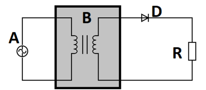
Figure 9: A half-wave rectifier: voltage supply (A), step-down transformer (B), diode (D), and resistor (R)
A diode allows the current to flow in one direction. During the negative cycle of the input voltage, a corresponding negative voltage is induced in the secondary side, and the diode doesn’t conduct. Hence, there is no flow through the output resistor during the negative cycle of the input voltage as the diode behaves as an open circuit (See Figure 10). Therefore the output gives only alternate positive cycles.
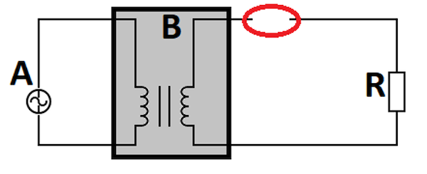
Figure 10: Diode acts as an open circuit during negative half cycle of input voltage: voltage supply (A), step-down transformer (B), and resistor (R)
For practical applications, a capacitor is connected at the output in parallel with the resistor (See Figure 11). The capacitor acts as a filter to smooth out the pulsating output voltage to the appropriate DC level (See Figure 12). Read our article on AC to DC transformers for more details.
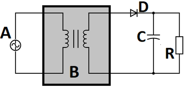
Figure 11: A half-wave rectifier with capacitor filter: voltage supply (A), step-down transformer (B), diode (D), capacitor (C), and resistor (R)
The waveforms at various points of the rectifier are shown in Figure 12.
- Vi: Alternating input voltage applied
- Vo1: Output of the diode consisting of alternate positive half-cycles
- Vo2: Capacitor output that is a smoother version of diode output, creating an accurate DC voltage.
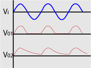
Figure 12: Half-wave rectifier waveforms showing input voltage, diode output, and capacitor outputs respectively
Isolation transformer
Isolation transformers are used to isolate two electrical circuits in an electrical system. An isolation transformer is similar to a conventional transformer with an equal number of turns in the primary and secondary windings, thereby creating equal voltage in the primary and secondary sides. Isolation transformers are used in electrical devices like computers, televisions, solid-state relay circuits, and industrial power electronic devices.
To isolate two circuits, ‘A’ and ‘B’ physically, the primary windings of the isolation transformer are connected to the circuit ‘A,’ and the secondary windings to circuit ‘B.’ The electric supply on the first circuit energizes the primary winding of the isolation transformer, which in turn creates a voltage and current in the secondary winding through mutual induction. As an isolation transformer does not change the value of current and voltage at the secondary windings, circuit ‘B’ receives the same magnitude of secondary current and voltage. Hence, circuits A and B are electrically isolated, yet energy is transferred between them, with the isolation transformer acting as a medium between them.
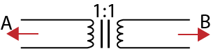
Figure 13: An isolation transformer connecting two circuits, A and B
Transformer applications
- Step-down transformers are used in home appliances, inverters, power distribution networks, and transmission lines to step down the voltage to the desired level.
- Step-up transformers are used to distribute electrical energy. These transformers are also used to run electric motors, X-ray machines, and microwave ovens.
- Instrument transformers like current transformers and voltage transformers are used to measure extremely high voltages in transmission lines and also as isolation devices in commercial metering devices.
- Single-phase transformers are used to step-up power in home inverters or step-down long-distance signals to support both residential and light-commercial electronic devices.
- Three-phase transformers are used for electric power generation and distribution network applications. They can be found in high-power industrial loads such as motor drives, rectifiers, and other equipment.


