


Three-Phase Transformers
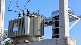
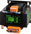
Figure 1: Three-phase transformer
Three-phase transformers are passive machines that pass electrical energy between circuits. In the secondary circuit, a magnetic flux induces an electromotive force (emf), thus stepping up (increase) or stepping down (decrease) voltages without altering the frequency. There are different kinds of electrical systems, and therefore transformers have to operate alongside compatible systems. A three-phase transformer works with a three-phase AC (alternating current) electrical system to provide consumers with stable and device-safe electricity. Depending on the industry or application, the size, design, volt-ampere rating, and load-bearing capabilities of the three-phase transformer will differ.
Table of contents
- What is a three-phase transformer?
- What is the three-phase electrical system?
- Significance of Faraday's law of induction
- Three-phase transformer types
- Three-phase transformer constitution
- Configurations
- Applications
- FAQs
View our online selection of transformers!
What is a three-phase transformer?
In some DC rectification transformers, voltage transformers can be constructed for a single-phase or two, three, six, and even complex combinations of up to 24-phases. Power generation, distribution, and transmission processes can use three-phase, denoted as 3φ or 3-phase. A 3-phase transformer works on a three-phase power supply and both primary and secondary windings have three sets of windings.
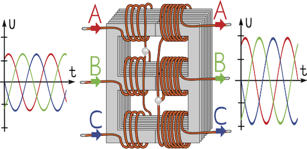
Figure 2: A three-phase transformer having three sets of windings (A, B, and C) on both primary and secondary sides
What is the three-phase electrical system?
Three-phase and single-phase electrical systems utilize alternating current (AC). AC is generally in the sine waveform, but other waveforms like square, triangle, and complex waves, can also be generated. AC signals have three significant properties: amplitude, period, and frequency. Amplitude describes the magnitude of the wave. The period is when one complete oscillation occurs, while the frequency is the number of cycles appearing per second.
A complete AC oscillation has both a peak and trough. For the usual 360° cycle, these points are at 90° and 270°. The 1-phase system has a single peak and trough within one conductor, and these points experience maximum magnitudes but in opposite directions. 3-phase systems, on the other hand, have three peaks and troughs on three conductors. Voltages and currents lead or lag each other by 120° (Figure 2).
Significance of Faraday's law of induction
The operation of all types of transformers is subject to Faraday's law of induction – it states that the magnitude of the emf induced within a circuit is directly proportional to the rate of change of the magnetic flux cutting across the circuit.
Therefore, a conductor placed near a changing magnetic field – from an AC-powered electromagnet, for instance – will have an electric current. Electromagnetic circuits of this nature are called primary windings.
As the electric current collapses and is generated continually at a particular frequency, the magnetic field collapses and recreates similarly. This alternating magnetic field induces a current in the conductors cut by this flux; they are then called secondary windings. The frequency is the same across both windings.
Three-phase transformer types
Three-phase transformers can be categorized depending on their construction. There are two types of 3-phase transformers: the core-type with primary and secondary windings wound on one core and the shell-type transformer that combines three 1-phase transformers.
Core-type
In core-type three-phase transformers, the core has three limbs within the same plane. Each limb contains primary and secondary windings, and these windings are evenly split among the three limbs. It's not uncommon to hear of high voltage (HV) and low voltage (LV) windings.
As a low voltage winding is easier to insulate, these windings are closer to the core than the higher voltage coils. The latter windings wrap around the former, with insulative material between them. This construction has the windings magnetically linked with one another, with one winding using the other pair of limbs as return paths for its magnetic flux (see Figure 3).
Shell-type
The shell-type 3-phase transformer is three separate 1-phase transformers. The three phases of this transformer have their magnetic fields virtually independent, and this transformer's core has five limbs.
The HV and LV windings exist around the three main limbs. Like the core-type 3-phase device, the low voltage coil is nearest the core. The two outermost limbs serve as the flux's return paths.
Magnetic flux divides in two as the field approaches the yoke. It's common for the outer limbs and the yoke to be half the size of the main limbs. You can decrease the transformer's height by reducing the yoke's size.
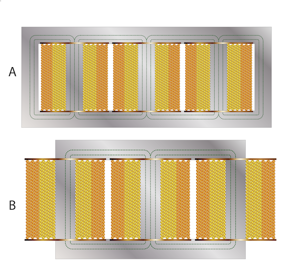
Figure 3: Shell-type (A) and core-type transformers (B)
The three-phase transformer constitution
Apart from core and windings, there are other vital parts in a transformer as discussed below:
- Insulation: This part acts as a barrier separating windings from the core.
- Transformer oil: The transformer oil has two main functions: insulation and cooling. The oil's insulation properties prevent electricity from shorting and arcing. This oil acts as a coolant by transporting away heat from the core and windings.
- Thermometers: Thermometers monitor the temperature of the oil.
- Pressure relief systems: Pressure relief systems are part of the safety protocol. They defuse overpressure situations when oil flashes because of short circuits.
- Cooler: The cooling system cools the coolant. It cools down the hot oil via water or air-cooled tubes. The coolant is then returned to the core and the windings.
- Tank: The tank protects the transformer windings and core from external conditions and holds the coolant.
- Oil conservator: The oil conservator is a vessel installed separately from the tank. It helps hold oil after it has expanded due to heating in windings and the core.
- Voltage regulators: Voltage regulators alter output voltage, which tends to decrease during loaded conditions. Modifying the tapping turns using a tap changer adjusts the voltage ratio.
- Gas-actuated relay: Gas-actuated relays have another name – the Buchholz relay. It holds released gas bubbling from the transformer tank, and seeing this free gas indicates there is a problem with the transformer.
- Breathers: Breathers work to keep the transformer oil dry. These breathers remove moisture from the air pockets above the conservator oil level.
Configurations
There are two significant connections for these three-phase machines; the star and delta configurations.
The star configuration is also called the wye connection. It has four terminals but three windings. The three windings form the circuit's three phases, while the fourth terminal is the terminal where the other three windings meet; it's a common neutral point.
Delta connection, also known as the mesh connection, is an interconnection of three windings whose ends are connected, creating a closed loop. It has three terminals and windings with no neural point, using grounding connections instead. The delta connection is configured into high-leg systems by grounding one phase's midpoint, as seen in Figure 4.
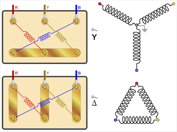
Figure 4: Star (left) and delta (right) connections
Voltage and current characteristics
There are pros and cons to using either star or delta 3-phase transformer wiring systems. Understanding the phase and line currents and voltages is paramount to choosing the right system for your applications.
Phase currents and voltages are measured over one component, whereas line parameters are measured over two terminals. Table 1 demonstrates the relationships between these characteristics:
Table 1: 3-phase voltage and current characteristics
| Connection | Phase voltage | Line voltage | Phase current | Line current |
| Star | VP = VL / √3 | VL = √3 * VP | IP = IL | IL = IP |
| Delta | VP = VL | VL = VP | IP = IL / √3 | IP = √3 * IL |
- VL: line-to-line voltage (line voltage)
- VP: phase-to-neutral voltage (phase voltage)
- IL: line current
- IP: phase current
In addition to voltages and currents, a 3-phase transformer calculator would require another parameter to properly size the device – the turns ratio (TR). As a transformer is a linear machine, voltages in the secondary windings can be determined using the primary voltages and the turns ratio. It is the ratio of the turns of the secondary and primary windings.
3-phase transformer winding diagrams
The primary and secondary windings in a three-phase transformer can either have different or the same configurations. The four main permutations include:
Star-star configuration (Y -Y)
The primary and secondary coils are wound in the star system. It has the major advantage of possessing a neutral terminal on the transformer's two sides, enabling grounding. Grounding removes distortion from the waveform. When ungrounded, the operation of this kind of transformer is satisfactory if the three loads on the three phases are balanced. It's mainly for small HV transformers.
TR = VS / VP = NS / NP = IP / IS
- VS: Secondary voltage
- VP: Primary voltage
- IS: Secondary current
- IP: Primary current
This connection reduces the number of turns since the phase voltage is 1/√3 of the line voltage. The amount of insulation required is also lowered.
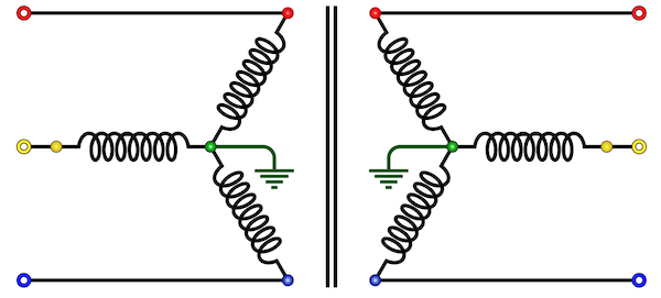
Figure 5: Star-star connection
Delta-delta configuration (Δ-Δ)
The primary and secondary coils are in the delta system. This system is for large LV transformers, and it utilizes a more significant number of turns than the Y-Y type. One advantage of this connection is that it's compatible with unbalanced loads on the phases. Another advantage is that even when the transformer is disabled, its 3-phase loads can remain powered. This is usually in the open delta configuration at reduced capacities.
In a delta-delta configuration:
TR = VS / VP = NS / NP = IP / IS
- VS: Secondary voltage
- VP: Primary voltage
- IS: Secondary current
- IP: Primary current
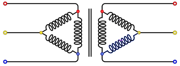
Figure 6: Delta-delta configuration
Wye-delta or Star-Delta configuration (Y-Δ)
In this configuration, the primary winding is star connected and grounded at its neutral terminal. The secondary turns are connected in the delta system. Its main application area is in the stepping down of voltages at the substation side of the electrical transmission.
Secondary and primary line voltages have a ratio that's 1/√3 times the device's transformation ratio. There's also a 30-degree shift between primary and secondary line voltages.
Delta-wye or Delta-star configuration (Δ-Y)
The primary winding connects in the delta system and the secondary in the grounded star configuration. It's mainly used in step-up transformers located where the transmission line originates. Secondary and primary line voltages have a ratio that's √3 times the device's transformation ratio. There's also a 30-degree shift between primary and secondary line voltages like the Wye-Delta transformer.
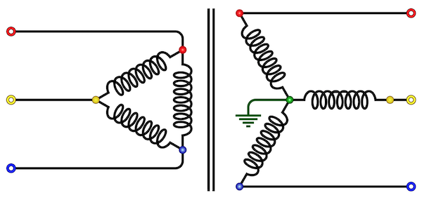
Figure 7: Delta-star configuration
There are two other configurations besides the four main permutations. These others are a product of altering primary delta and star windings. They include:
Open delta (V-V) connection
Two transformers are in this system. The V-V connection comes into play when one of the transformers is disabled, but regular load operation is still required. Service will continue until it needs repairs or a replacement installed in such cases.
This configuration can support small three-phase loads where installing a complete three-phase transformer bank is unnecessary. Its carrying capacity is 57.7% of the full delta-delta connection.
Scott-T (T-T) connection
In this 3-phase transformer winding system, two transformers are utilized. One has center taps on primary and secondary windings, known as the main transformer. The other transformer, called the teaser transformer, has a 0.87 tap. The teaser transformer operates at 87% of the rated voltage.
It's used when a three-phase system interlinks with a two-phase system. Powering an electric furnace that works on a two-phase system is a typical application of a T-T connection.
High leg delta connection
A high leg delta connection occurs when the delta-connected secondary side is center-tapped; this tap then connects to the ground. Such a configuration produces a 3-phase supply (delta-connected) and a 1-phase supply.
Both commercial and residential distribution systems utilize this connection. Consumers can receive 240 V (line voltage) for large machines or 120 V (phase voltage) for smaller equipment or lighting without requiring an additional transformer.
Applications
Three-phase transformers are versatile machines that find their use in many fields. Some of the more common applications include:
- Power generation and transmission processes utilize three-phase transformers.
- Three-phase transformers can step up/step down voltages in many industries. These transformers are widely used in mining, printing, textile working, elevator, industrial automation, and petrochemical fields, among several others.
- As the three-phase transformer can exempt noise and high-frequency pulse interference from its internal coupling, they are essential when making precision machine tools. Present in high power industrial load systems, such as motor drives and rectifiers, among other equipment.
FAQs
Can a three-phase transformer use a single-phase source to deliver three-phase power?
It is impossible to transform single-phase input voltages to supply three-phase power at the transformer's output. Phase-shifting machines or phase converters such as capacitors and reactors are needed when converting a single-phase system into a three-phase one.
Can three-phase transformers be operated at frequencies higher than the rated frequency?
It is possible to use three-phase transformers at frequencies higher than the rated. But the higher the frequency is past the rated value, the more reduced the voltage regulation.
What does impedance mean when talking about three-phase transformers?
Impedance is a current opposition/limiting characteristic of the transformer, and it's usually expressed as a percentage. This parameter determines a fuse or a circuit-breaker's interrupting capacity to protect the transformer's primary windings.


