


What are Step-up and Step-down Transformers?
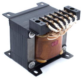
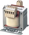
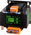
Figure 1: Transformer
Transformers are static devices that are essential for the efficient transfer of electric power from one circuit to another. As power moves through a transformer, the voltage that enters the input, or the primary end, is altered to fulfill the specific need at the output or secondary end. In a step-up transformer, the voltage level is raised at the output, whereas In a step-down transformer, the voltage level is reduced. This article discusses the structure and use of step-up and step-down transformers, along with some principles governing the transmission of electricity.
Table of contents
- What are step-up and step-down transformers?
- Transformer working principle
- Step-up transformer working principle
- Step-down transformer working principle
- Reversibility of transformer operation
- Applications
- FAQs
View our online selection of transformers!
What are step-up and step-down transformers?
A step-up transformer increases the input voltage and delivers it to the load, and a step-down transformer decreases the input voltage at the load. High voltage is required for efficient power transmission, but the power must be utilized by consumers at a lower voltage for safety reasons. The transition from low voltage to high for transmission requires a step-up transformer. In some countries, step-up transformers are invaluable. For example, the power generation level in India is 11kv; hence, step-up transformers are required at the generating stations. In short, a step-up transformer raises the voltage for transmission purposes.
Step-down transformers convert high voltage power to a low voltage. This makes the power level suitable to the requirements of each device connected to the power systems at household or business locations. Power circuits for homes carry 230V -110V, but some features require as little as 16V. So step-down transformers are needed to reduce the voltage to the lower power level.
Additionally, separate circuits in electrical systems within homes and businesses usually share the same frequency. But often, the voltage needs differ. Therefore, smaller step-up or step-down transformers are included in the design of many household appliances. Step-up and step-down transformers can be either single-phase or three-phase transformers, depending on the type of power supply used. Step-up and Step-down transformers serve different purposes and are designed in many configurations, depending upon the needs of each specific situation.
Transformer working principle
A transformer consists of two sets of wires (see Figure 2):
- The primary winding (A): collects power
- Secondary winding (B): provides power
The primary and secondary windings are wound together on a magnetic iron circuit core, but these coils are not in contact with one another, as seen in Figure 2. The core is made of a soft magnetic material consisting of laminations (Figure 2 labeled C) linked together to help reduce core loss. Core loss is the energy loss within the core caused by an alternating magnetic flux. An unstable magnetic field eventually destroys the core material's functioning.
When the primary winding (Figure 2 labeled A) is connected to a power supply, current flows through the coil, and a magnetic field is induced. A part of this magnetic field links with the secondary windings (Figure 2 labeled B) by mutual induction, thereby producing a current flow and voltage at the secondary (load) side. The voltage produced at the load side is proportional to the number of turns in the secondary winding relative to that on the primary side. The voltage transformation is given by,
V1 / V2 = N1 / N2 = I2 / I1
- V1: Voltage applied to the transformer primary winding
- V2: Voltage produced at the secondary (load) winding of the transformer
- N1: Number of turns in the primary winding
- N2: Number of turns in the secondary winding
- I2: Current flowing through the secondary windings
- I1: Current flowing through the primary windings
Read our electrical transformer overview article for more details on the construction and the various ways to connect a transformer.
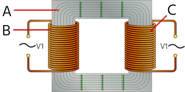
Figure 2: Construction of a transformer showing primary windings (A), secondary windings (B), and magnetic core (C)
Step-up transformer working principle
A step-up transformer increases the voltage at the secondary windings relative to the primary side. From the equation for voltage transformation, for V2 to be greater than V1, the value of N2 should be greater than N1 (See Figure 3). Therefore, in a step-up transformer,
- N2 > N1
- V2 > V1
- I2 < I1
A step-up transformer always steps down the current (while stepping up the voltage) at the secondary side relative to that on the primary side. This is because the total power at the transformer's primary and secondary sides are equal. The thickness of the transformer coils depends upon the capacity of the current it is designed to carry. In a step-up transformer, the primary side carries more current; hence, thick insulated copper wire is used for the primary winding and thin insulated copper wire for the secondary side. A transformer is usually rated by the product of voltage and current as kVA (kilo-volt amperes). Read our article on transformer calculator for more details on the power associated with a transformer.
Example
If a 1:10 transformer is applied 10V at the primary winding,
- N1 = 1
- N2 = 10
- V1 = 10V
- Therefore, V2 = (N2 / N1) ✕ V1 = 100V
The voltage at the secondary side of the transformer is ten times that applied at the primary side.
Advantages
- Easy maintenance
- High efficiency
- Quick start
- Power transmitter
Disadvantages
- Requires a cooling system
- Works only on alternating current (AC) signals
- Huge size
Step-down transformer working principle
A step-down transformer decreases the voltage at the secondary windings relative to the primary side. From the equation for voltage transformation, for V2 to be less than V1, the value of N2 should be less than N1. Therefore, in a step-down transformer,
- N2 < N1
- V2 < V1
- I2 > I1
A step-down transformer always steps up the current (while stepping down the voltage) at the secondary side relative to that on the primary side. In a step-down transformer, the secondary side carries more current; hence, thick insulated copper wire is used for the secondary winding, thin insulated copper wire for the primary side. Step-down transformers are commonly used in low voltage transformers for landscape lighting applications.
Example
If a 100:1 transformer is applied 10V at the primary winding,
- N1 = 100
- N2 = 1
- V1 = 10V
- Therefore, V2 = (N2 / N1) ✕ V1 = 0.1V
The voltage on the secondary side of the transformer is 100 times less when compared to the voltage applied on the primary side.
Advantages
- High durability and reliability
- Less cost
- High efficiency
- Provides different voltage supplies for common household applications
Disadvantages
- Requires high maintenance
- Works on only AC
Reversibility of transformer operation
Step-up and step-down power transforming functions can be accomplished using the same transformer. The difference in operation lies in how the transformer is connected to the circuit. If the input supply is accomplished on the low-voltage winding, the transformer functions as a step-up version. The same transformer can be utilized as a step-down version of the input supply if it is connected to the high-voltage winding.
Applications
Step-up transformers
- Step-up transformers with primary side windings of thick insulated copper wire that raise the voltage to 11000 volts or more are required for users with special power requirements, like X-ray machine operation, microwave, and power plant applications.
- Step-up transformers are used to distribute electrical energy in high-power transmission lines.
- These transformers are used to boost electronic devices.
Step-down transformers
Step-down transformers are commonly used in:
- Common household equipment like CDs, television, and doorbells.
- Voltage stabilizers
- Inverters
- Power distribution networks
- Mobile phone charges
- Transmission lines
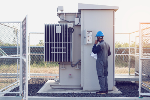
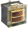
Figure 3: Step-up high voltage transformer
FAQs
What is the primary scientific principle behind transformer operation?
A transformer works on mutual induction, which states that a current-carrying coil produces a proportional magnetic field and vice-versa.
Is a different type of transformer required to step-up or step-down power?
The same type of transformer can be used for either purpose. The function of a transformer depends upon how it is set up within a circuit.


