G1'' T-port 3-Way Stainless Steel Electric Ball Valve 12V DC - BL3SA
3 Way electric ball valve (T-port) with G1 inch pipe threads and powerful and energy efficient 12V AC/DC actuator (max 40Nm). Media from -20 to 130°C, max pressure 63 bar at 20°C. Stainless Steel valve housing with stainless steel ball and PTFE/FKM valve seats. The nominal diameter is 20mm, the Kv-value is 27m3/h (450 l/min water at dP=1 bar). 3-point control. Rotation 0-90° in only 8 sec. Compact and strong actuator housing (IP67) with position indicator. Manual override function and two extra limit switches for position feedback.
- Regular price
- $563.69 USD
We sell only to registered businesses
Description
This strong and energy efficient 3-way (T-port) electrical ball valve from Tameson can be used to automatically shut of pipes with gas or fluids. The valve has 1 inch pipe threads (internal thread, BSPP). The housing of the valve is made of stainless steel with a stainless steel ball and PTFE (teflon)/FKM sealing. The actuator is suitable for both 12 volt DC (direct current) and 12 volt AC 50/60Hz (alternating current). With switches on the circuit board, the actuator can be set for AC or DC. The factory default setting is direct current (DC). The actuator has a robust aluminium housing (IP67, provided that an appropriate cable is connected) and delivers maximally 40 Nm torque. The valve rotates from 0 to 90 degrees in 8 seconds. When the ball reaches an end position, the electric motor is turned off and no energy is consumed. The actuator is equipped with two additional limit switches for position-feedback. The limit switches are positioned at 0 and 90 degrees. If required, the angular position of the switches can be adjusted by the user. A mechanical position indicator on the top of the actuator shows the valve position. The actuator is equipped with a manual override.
Key benefits
- Robust stainless steel ball valve with 1 inch pipe threads
- Switching time only 8 seconds
- Strong IP67 actuator housing
- Both 12V AC and DC possible (set by switch)
- Two extra limit switches for position feedback
- Manual override control
- Clear visual position indicator
Technical specifications
| Actuator | Ball Valve | ||
|---|---|---|---|
| Actuator ref: | AG-040-C | Ball Valve ref: | BL3SAT-100 |
| Voltage: | 12V DC/AC (50/60Hz) | Housing: | Stainless steel (AISI 316) |
| Nom./Max. Current: | 0.2/2.2 A | Ball: | stainless steel (AISI 316) |
| Protection: | IP67 | Seat rings: | PTFE (teflon)/FKM |
| Duty Cycle: | S2 30min. | Pipe threads: | G1" BSP |
| Open/Close: | 7 s | Nominal Diameter: | 20mm (DN) |
| Amb. Temp.: | -10°C..50°C | Installation length: | 108 mm |
| Range: | 0-90° | Max pressure (@20°C): | 63 bar |
| Extra limit switches: | 2 | Function: | 3-way T-port |
| Manual override: | Yes | Temp medium: | -20°C..130°C |
Bore and circuit function
The ball has a T-port. By rotating the ball 90 degrees, can be switches between two circuits or can the three pipes be connected. The ports overlap during rotation.

Schematical drawing of the circuit function of T-port valves
Dimensions

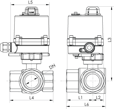
Dimensions of the AG-040-C actuator and BL3SAT-100 ball valve.
Applications
This valve can be used in combination with gases and fluids. The valve is durable and suitable for different aggressive and corrosive media. The maximum pressure at room temperature is 63 bar, at higher temperatures the maximum allowed temperature decreases. The direction of pressure is not important, the direction of flow may be in any direction. The temperature range of the medium lies between -20°C and 130°C. At high temperatures, it is recommended to install the valve in a ventilated area. It is allowed to install the valve in a humid environment provided that all parts, like an appropriate electrical cable, are correctly fixed. Ball valves can be used with light contaminated fluids. Some examples of applications for this valve are HVAC, irrigation, industrial automation, water management.
Electrical Wiring Diagram
Follow the safety instructions and manual before you start installation.The actuator works with 12 volt DC and 12 volt AC (50/60Hz). On the PCB are two small switches to set the actuator to AC or DC. The default setting is DC. The actuator draws 0.2A nominal, and 2.2A at maximal torque. The actuator has 3-point control. Terminals 1 (minus) and 2 (plus) are permanently connected to the power supply. Terminals 3 (minus) and 4 (minus) are for the control signals. Connecting one of these control wires, closes or opens the valve. Never connect terminals 3 and 4 at the same time to prevent short circuit and damage. The actuator has two internal limit switches. As soon as the actuator's end position is reached (0 or 90 degrees), the motor turns off and no energy is consumed. In addition, in the actuator there are two additional limit switches for control purposes. The angular position of the limiti switches can be modified. Always connect the earth and do not use the pipes as ground.


Electrical wiring diagram of the AG-040-C actuator. Before using alternating current, first the switches on the PCB need te be set.
Assembly
Make sure that the position of the ball and the actuator are properly set before assembly. The actuator is provided with two adapters to connect the actuator to the valve shaft. Mount the actuator to the valve with the provided bolts. There should be no play between both flange. Use our fittings range for the connection between the pipe and the valve.
In the box
- Actuator AG-040-C (cable not included)
- Drive shaft adapter (9x9mm, 11x11mm)
- 4 bolts M5x16mm & spring washers (for F03 flange)
- 4 bolts M6x16mm & spring washers (for F04 & F05 flange)
- Ball Valve BL3SAT-100
Note: This product is delivered in separate parts, but with the required mounting accessories.`


