Understanding pressure measurement accuracy
Even the best measuring equipment produces a certain deviation from the actual value. It is important to know how this measurement accuracy is defined. In this article we explain the basic principles of different measurement deviations and how they are defined. For many pressure transducers, the overall accuracy value is expressed as a percentage of the measurement span. The overall accuracy is a combined effect of:
- Non-linearity
- Hysteresis
- Zero offset and span error
- End value deviation
These different accuracy influencing factors are explained in detail in the following paragraphs.
Table of contents
- Characteristic curve
- Maximum measuring error
- Non-linearity
- Hysteresis
- Zero offset and span error
- Non-repeatability
- Temperature error
- Temperature hysteresis
- Long-term drift
Characteristic curve
The characteristic curve represents the relation between the input and output signal. In the ideal situation, the output signal linearly depends on the input signal. This would mean that the characteristic curve is a straight line. This however is not the case, the characteristic curve deviates from the ideal straight line.
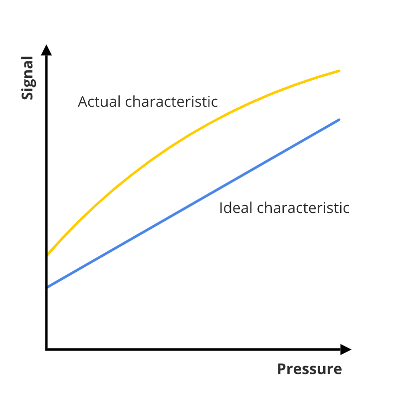
The accuracy is often defined as the deviation of the characteristic curve from the ideal line. The accuracy for pressures sensors is defined differently. IEC 61298-2 states that the accuracy should include Hysteresis, Non-Repeatability and Non-Linearity. To determine the total measuring error, other deviations are also taken into account. These measuring errors normally are defined as a percentage of the span (e.g. ±1 % of span). The span is defined as the difference between the minimum and maximum signal value. For example, the span of a 4-20 mA signal is 16 mA.
Maximum measuring error
One way to define accuracy is to look at the maximum measuring error. The maximum measuring error is the maximum deviation of the characteristic curve from the ideal line at a defined temperature.
Non-linearity
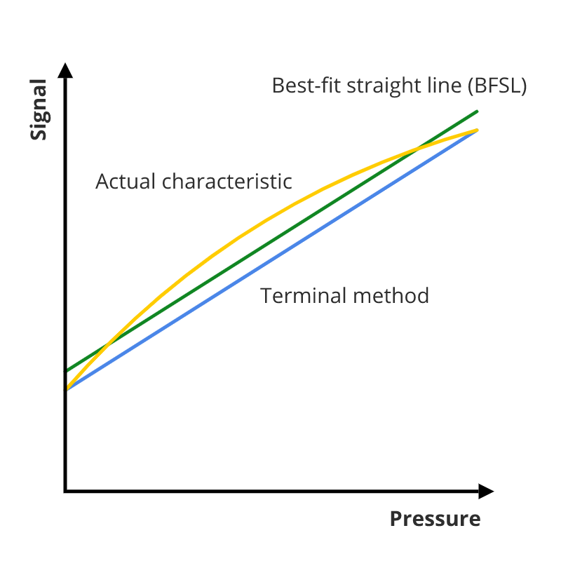
The non-linearity is referred to as the largest possible deviation (positive or negative) of the characteristic curve from a reference straight line. Different methods exist to determine the reference straight line. The terminal method and the best-fit straight line (BFSL) method are the most used ones. For the terminal method the reference line passes the start and end points of the characteristic curve. The BFSL reference line is determined using the least squares method. The terminal method commonly results in a twice as large deviation as the BSFL method. When comparing measuring instruments it is important to check if the same method is used.
Hysteresis
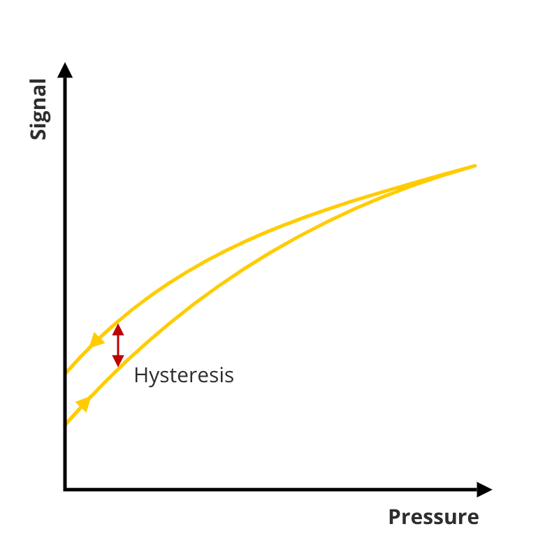
The characteristic curve is recorded by gradually increasing the pressure followed by gradually decreasing the pressure. The recording will show that the pressure increase and decrease lines don’t exactly match. The maximum difference between those two curves is called the hysteresis. Hysteresis is caused by the elastic properties of the instrument’s material and the design of the instruments itself. This error cannot be reduced by the user. If lower hysteresis errors are needed, the manufacturer needs to be contacted.
Zero offset and span error
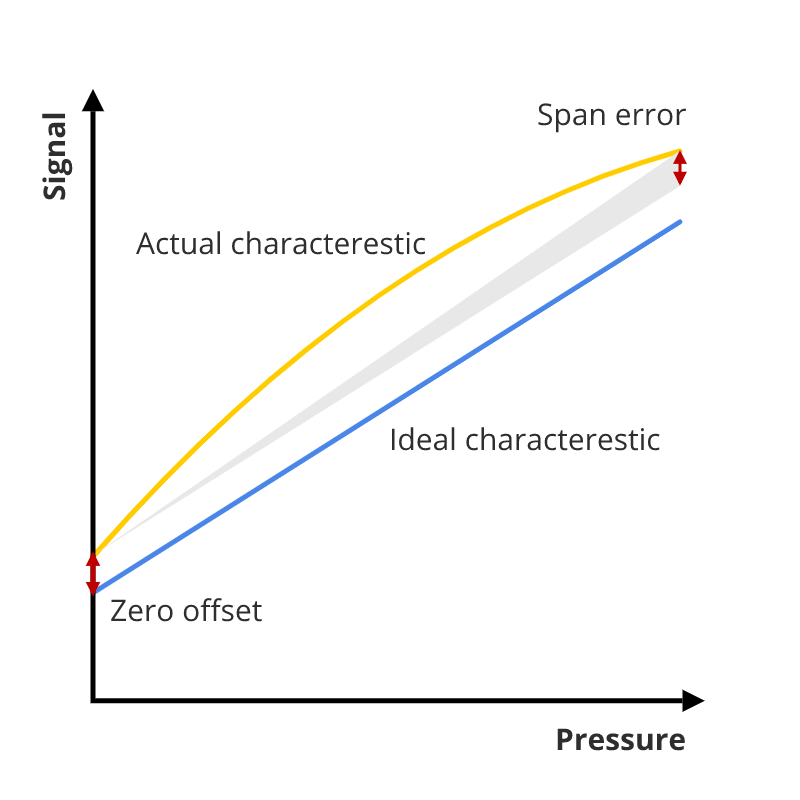
The output’s zero and end point can differ from the ideal line’s zero and end point. The zero offset error and the span error are the deviations between the actual and ideal values of the zero and end point of the signal.
Non-repeatability
The output signal for consecutive measurements of the same pressure value is not always exactly the same. This variability or error is called the non-repeatability. It is defined as the largest deviation during three consecutive measurements under constant identical conditions (IEC 61298-2), or simpler: the difference between the lowest and largest value of the consecutive output signals. A reliable instrument or sensor should have a small non-repeatability.
Temperature error
The temperature has a direct influence on the output signal. Temperature changes influence the electronics of the measurement instrument. If the temperature increases, the electrical resistance of conductive metals increases, while it decreases for semiconductors. Furthermore, most materials will expand when the temperature increases.
Counter measures
In order to minimize the temperature error, manufacturers balance the thermal characteristics. This compensation is done directly on the sensor or electronically. The temperature error cannot be completely eliminated. The residual error is given commonly expressed as a percentage of the full span for a defined temperature range with respect to a reference temperature.
Temperature hysteresis
In addition to the temperature error there also is temperature hysteresis. Temperature hysteresis is similar to normal hysteresis, but here it is caused by a temperature increase and decrease instead of pressure changes.
Long-term drift
The characteristics curve of a measuring instrument is not constant throughout its service life. The characteristics will change over time due to mechanical and thermal influences. This slow change of characteristics over a long time is called the long-term drift. Long-term drift is determined by testing. Since different manufacturers use different testing procedures, long-term drift information should not be compared. The tests are performed using reference conditions. This can cause significant differences if the operational conditions differ from the reference conditions.


