


Pneumatic Time Delay Valves
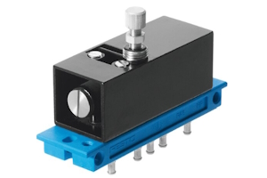
Figure 1: A Festo pneumatic time delay valve.
A pneumatic time delay valve regulates the timing of air flow in a pneumatic system by delaying the activation or deactivation of the valve for a specified duration. Time delay valves are crucial components in industrial systems where precise timing is essential for optimal performance. These valves are used in various industrial applications, such as automated machinery and safety systems. This article will use Festo time delay valves as an example to illustrate their features and selection criteria.
Pneumatic time valves often work with 3/2-way pneumatic directional control valves to control the timing and direction of airflow in a pneumatic system. The 3/2-way valve has three ports and two positions, allowing it to either direct air to an actuator or exhaust it. The pneumatic time delay valve regulates the duration of airflow, ensuring precise control over the timing of operations. This combination is used to automate processes, improve efficiency, and ensure accurate timing in applications such as machinery, manufacturing, and fluid control systems.
Design components
Figure 2 illustrates the typical components of a time delay valve:
- Timing adjustment knob (A): Allows the user to set the desired delay time by adjusting the internal mechanism. The adjustment knob is a throttle valve, typically a needle valve.
- Exhaust port (B): Releases excess air from the control chamber to reset the valve for the next cycle.
- Inlet port (C): The entry point for the compressed air that will be controlled by the valve.
- Non-return valve (D): Air from the inlet flows through a non-return valve into the control chamber.
- Control chamber (E): The internal space where air pressure builds up to create the delay effect.
- Diaphragm or piston (F): Moves in response to air pressure changes, controlling the flow of air through the valve.
- Outlet ports (G): The exit points where the controlled air is released after the delay period.
- Spring mechanism (H): Provides the necessary force to return the diaphragm or piston to its original position after the delay period.
- Valve body (I): The main structure that houses all internal components and provides connection points for the inlet and outlet ports.
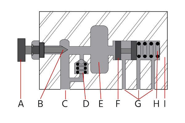
Figure 2: The typical components of a pneumatic time valve: timing adjustment knob (A), exhaust port (B), inlet port (C), non-return valve (D), control chamber (E), diaphragm or piston (F), outlet ports (G), spring mechanism (H), and valve body (I).
Operating principle
- Air supply: Compressed air enters the valve through the inlet port.
- Timer mechanism: The valve contains a timer mechanism, usually a diaphragm or piston, connected to an adjustable needle valve. The needle valve controls the rate at which air fills or exhausts from the control chamber.
- Delay period: When air enters the control chamber, the needle valve restricts the flow, creating a delay. The length of the delay is adjustable by changing the needle valve setting using the timing adjustment knob.
- Activation: Once the control chamber is filled to a certain pressure, it triggers the main valve to open or close, allowing air to pass through or be blocked.
- Output: The delayed air flow then activates or deactivates the connected pneumatic component.
- Reset: Excess air is released through the exhaust port, resetting the valve for the next cycle.
Time delay valve applications
Pneumatic time delay valves are used in various industrial settings where precise timing is essential. Below are common applications:
- Automated machinery: Time delay valves control the timing of different machine operations, ensuring that each step occurs in the correct sequence.
- Safety systems: These valves provide a delay before activating safety mechanisms, allowing for controlled shutdowns or emergency responses.
- Sequential operations: Time delay valves manage the timing between sequential tasks, ensuring that each task is completed before the next one begins.
- Conveyor systems: They regulate the timing of item movement on conveyors, preventing jams and ensuring smooth operation.
- Packaging equipment: Time delay valves control the timing of packaging processes, such as sealing and labeling, to maintain consistency and efficiency.
- Pneumatic control circuits: These valves introduce delays in pneumatic circuits to control the timing of air flow and pressure changes.
- Process control systems: Time delay valves ensure that processes occur in the correct order and at the right intervals, improving overall system performance.
- Material handling systems: They manage the timing of material transfer and handling operations, optimizing workflow and reducing the risk of errors.
Example - Festo time delay valve
To give an example of time delay valves, this section overviews four of these devices from Festo:
- VZO-3-PK-3
- VZ-3-PK-3
- VZA-3-1/4
- VZB-3-1/4
A primary difference between these two devices is that the VZO is normally open, and the VZ is normally closed. This difference is important to understand because the poppet in the valve is spring-return. For safety reasons, it's essential to know if the valve will be open or closed in the event of power loss or leakage from the device.
Table 1: Key properties of Festo time delay valves
| Factor | VZO-3-PK-3 | VZ-3-PK-3 | VZA-3-1/4 | VZB-3-1/4 |
| Nominal size | 2 mm |
- | - | |
| Design structure | Poppet valve with spring return |
- | - | |
| Operating pressure | 2.5 to 8 bar |
0 to 10 bar |
||
| Adjustable delay times | 0.25 to 5 seconds |
0 to 30 seconds |
||
| Weight | 150 g |
550 g | 390 g | |
| Material housing | Zinc die-casting |
- | - | |
| Standard nominal flow rate | 60 l/min | 90 l/min | 600 l/min |
|
| Pause period for reset | >= 50 ms | >= 55 ms | - | - |
Selection criteria
When selecting a time delay valve, consider the following criteria to ensure optimal performance and compatibility with the system:
- Nominal size: Ensure the valve's nominal size matches the system requirements.
- Type of actuation: Determine if a pneumatic actuation is suitable for the application.
- Design structure: Choose a valve with an appropriate design structure.
- Operating pressure: Verify that the valve can operate within the system's pressure range.
- Flow rate: Ensure the valve's flow rate meets the system's needs.
- Adjustable delay times: Check if the valve offers the required delay times.
- Repetition accuracy: Consider the repetition accuracy of the time setting.
- Operating medium: Confirm that the valve is compatible with the operating medium. The VZO and VZ valves use compressed air in accordance with ISO8573-1:2010 [7:4:4].
- Environmental conditions: Ensure the valve can operate within the ambient temperature range of the environment. The VZO and VZ valves operate between -10 and 60 °C.
- Mounting type: Choose a valve with a suitable mounting type. The VZO and VZ valves can be installed on a front panel or mounting frame.
- Material and durability: Consider the material of the valve for durability and compatibility.
- Additional features: Look for any additional features that may be beneficial, such as the ability to connect an additional reservoir for longer delays.
FAQs
What is a pneumatic time delay valve?
A pneumatic time delay valve regulates the timing of air flow in a pneumatic system by delaying the activation or deactivation of the valve for a specified duration.
Where are pneumatic time delay valves used?
Pneumatic time delay valves are used in automated machinery, safety systems, and industrial applications requiring precise timing for optimal performance.