


Grounding Rods - How They Work
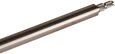
Figure 1: Ground rod for mobile objects like vehicles
Ground rods are critical in electrical grounding systems, providing a safe pathway for excess electricity dissipating into the earth. These rods protect people and electrical equipment from potential harm caused by lightning strikes or power surges. This article explores the design and installation of ground rods.
Table of contents
- What is a grounding rod
- Materials
- How to install a ground rod
- Ground rod installation requirements
- FAQs
View our online selection of ground rods!
What is a grounding rod
A ground rod (Figure 2 labeled E) is a long metal rod driven into the ground to provide a path for electrical current to disperse into the earth. When a fault occurs, such as a lightning strike or a malfunction in the electrical system, the excess electrical energy needs a safe path to dissipate. A grounding rod helps to prevent the dangers associated with static discharge voltages, such as lightning, thereby reducing the risk of harm during storms. It is connected to the electrical system's service panel via a grounding wire (Figure 2 labeled F), ensuring a safe path for excess electricity to the earth. Read our grounding overview article for more details on how electrical grounding works.
Note: Earthing spike is a more specific term that refers to a device specifically designed for grounding mobile objects such as vehicles, power generators, and other similar devices.
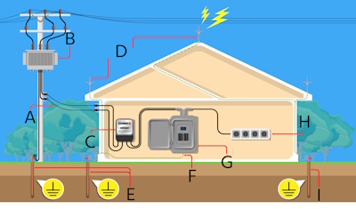
Figure 2: Electric power distribution system: service wire (A), transformer (B), electric meter (C), lightning rod (D), ground rod (E & I), ground wire (F), electric breaker panel (G), and appliances load socket (H).
Materials
Ground rods can be made from different materials.
- Copper: Copper is typically the most commonly used material for a ground rod. These rods are created by coating a steel core with copper. Copper-clad ground rods have a longer lifespan than those made from other materials.
- Stainless steel: Ground rods made from stainless steel are expensive but highly corrosion-resistant. Therefore, it is ideal for environments with high salt content.
- Galvanized steel: Galvanized steel ground rods are produced by applying a protective zinc coating to a steel base to guard against rust. These represent a more economical alternative among ground rods, though they do not match the reliability of copper options. Factors such as salt exposure can erode the zinc layer, resulting in an estimated service life of about 15 years, significantly shorter than the approximately 40-year lifespan of copper ground rods.
How to install a ground rod
Materials required
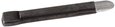
Proper selection and usage of equipment and materials are crucial for a safe and successful ground rod installation.
- Ground rod: The primary grounding element
- Earth pit or inspection chamber: A protective housing that attaches to the ground rod, shielding it from the environment and facilitating future maintenance and inspections.
- Ground rod clamp: A component designed to affix the ground rod within the earth pit or inspection chamber. Often constructed from copper or similarly conductive material, the clamp ensures a secure connection with minimal electrical resistance.
- Earth-enhancing compound: A material that enhances the soil's electrical conductivity and decreases ground resistance. This compound is typically spread around the ground rod to boost the grounding system's performance.
- Shovel or post-hole digger: A shover or post-hole digger is necessary to dig the hole the rod will go into.
- Additional tools and materials might also be needed, such as a rod-driving hammer and high-conductivity couplers for extending the ground rod.
Figure 3: Inspection pit for buried earth rod
Installation process
Figure 4: Ground rod installation: ground wire (A), ground rod (B), control cap (C), access well (D), and ground enhancement material (E).
- Location selection: Ensure the location is clear of underground utility lines to prevent any damage during installation. This site should be chosen based on various considerations outlined in the grounding system design.
- Assessing soil resistivity: Evaluate the soil's resistivity and consider any necessary soil treatments. The higher the soil resistivity, the less effective the grounding will be, and additional rods or deeper penetration may be required. Depending on the soil's resistivity and the site's specifics, the ground rod may be directly installed into the earth, or an earth-enhancing compound might be used to decrease ground resistance.
- Hole excavation: Use a shovel or post-hole digger to create a hole for the ground rod. This hole must be sufficiently deep to drive the rod at least 8 feet (2.45 m) below the surface. Typically, a hole with a diameter of 120 to 150 mm and a depth of 2.4 m is adequate for inserting the ground rod, although this may vary based on the rod's size.
- Rod insertion: Position the ground rod in the prepared hole and drive it into place with a hammer or sledgehammer. Ensure the rod is driven straight to guarantee effective grounding. All packaging should be removed from the rod, and the pointed end should be oriented downward. After installing the rod, connect a grounding wire to its top using a grounding clamp. This wire should extend to the electrical panel or another grounding junction.
- Using the grounding clamp: Extend the grounding wire to the electrical panel or an alternate grounding point and fasten it securely with the appropriate grounding clamp (Figure 5).
- Applying earth-enhancing compound: Mix the earth-enhancing compound (Figure 4 labeled E) with water to create a slurry as instructed by the manufacturer. Thoroughly pour the slurry into the hole to ensure complete filling. Without a ground-enhancing compound, the hole may be refilled with the excavated soil. If a compound is used, allow it to cure or set within the hole. The grounding site is then ready for connection use after 1-2 days post-installation once the resistance value has been checked.
- Installing ground pit/inspection chamber: Install the ground pit or inspection chamber (Figure 3) over the ground rod to offer protection against environmental elements and simplify future maintenance and inspections.
Figure 5: Connecting the grounding wire to the rod using a clamp
Ground rod installation requirements
Ground rod sizing
- Length: When installed vertically, the ground rod must be driven at least eight feet (2.45 m) deep into the soil, meaning the length of the rod extending below the ground surface should not be shorter than eight feet from the surface. This ensures that the rod is in contact with moist soil, which has lower resistance than dry soil. Grounding rod sizing regulations necessitate that the standard length for residential use is usually 8 feet, while for commercial or industrial applications or in areas with high soil resistivity, longer rods may be required for effective grounding.
- Diameter: Common diameters for ground rods range from 1/2 inch to 3/4 inch (15 - 23 cm). Larger diameters have a lower resistance to earth but are more expensive and more difficult to drive into the ground.
Other considerations
- Soil conditions: Soil resistivity plays a significant role in the effectiveness of a ground rod. In rocky or very dry soils, achieving an 8-foot depth for grounding rod may be challenging, and alternative methods like horizontal installation or using multiple rods might be necessary. Read our article on ground plate vs rods for different soil types to know more about how various soil types affect the selection of ground electrodes.
- Placement: While there are no exact rules for placing a ground rod, it is advisable to position it at a minimum distance of two feet from any building structure to prevent potential disruptions. Installing the ground rod near the home's electrical panel is also recommended. The ground rod location should be accessible and provide sufficient space for easy installation.
- Tools: The ground rod should be driven into the ground using a hammer or a driving rod. Do not use a digging tool, as this could damage the rod.
- Connection to the grounding wire: The ground rod must be connected to the electrical grounding system of the building or structure using a grounding conductor. The grounding conductor must be at least 8 feet long and made of copper or galvanized steel.
- Multiple rods: The total grounding system design might require more than one ground rod for adequate grounding. When multiple rods are used, they should be spaced at least 6 feet apart, according to the NEC.
FAQs
How deep should a ground rod be?
A ground rod should be driven into the ground to a depth of at least 8 feet (2.45 meters).
How far apart do ground rods need to be?
Ground rods should be spaced at least 6 feet (1.83 meters) apart.
Can rebar be used as a grounding rod?
Rebar is steel reinforcement used in concrete to provide strength. The rebar can be used as a grounding rod but is more prone to corrosion.

