


Directional Control Valve - How They Work
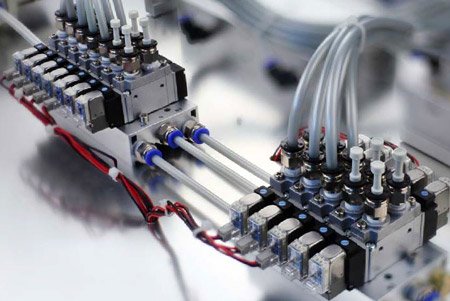
Figure 1: Pneumatic control valves on a manifold
Directional control valves direct the flow of compressed air or oil to various devices in pneumatic systems. They are used in various applications, like operating cylinders, larger industrial valves, or air tools. These valves have multiple ports and perform different functions within a circuit. Directional control valves can be actuated through various methods, like manually or using a solenoid. This article explores the various types of solenoid-operated directional control valves used in pneumatic systems.
Table of contents
- How does a directional control valve work
- Power consumption and operation mechanism
- Application considerations
- Mono-stable and bi-stable valves
- Pneumatic directional control valve types
- Namur standard
How does a directional control valve work
Pneumatic solenoid valves generally have a spool design. They consist of an aluminum body with a cylindrical hole. The different ports of the valve connect to the cylinder. A sliding spool in the cylinder has several seals along its length. By sliding the spool back and forth through the cylinder, different ports can be connected or closed off. It's difficult to create a sealing with absolutely no leakage with the spool design. Therefore, pneumatic solenoid valves always have a very small (but acceptable) internal leakage. Also, these valves are bidirectional.
Power consumption and operation mechanism
Pneumatic solenoid valves have low power consumption. This is primarily due to the relatively small force required to move the spool within the valve body. The air pressure exerted on the spool has a limited impact on this force, making the operation of these valves less power-intensive. Additionally, the force exerted by the spring in monostable valves (valves that return to a default position when not actuated) is minimal, further reducing the energy required for operation.
Operation mechanism
The operation of pneumatic solenoid valves is often facilitated by a pilot operation mechanism, which can be either direct or indirect (pilot operated):
- Pilot operated valves: In this design, the solenoid does not directly actuate the valve. Instead, it controls the air pressure that actuates the valve. This indirect method significantly reduces the force required from the solenoid, as the bulk of the actuating force is derived from the air pressure itself. This system allows for the use of smaller, more energy-efficient solenoids, contributing to the overall energy efficiency of the valve.
-
Internally vs externally piloted: Pneumatic solenoid valves can be internally or externally piloted.
- Internally piloted valves use the air pressure entering the valve for actuation, needing a differential pressure between 0.1 and 1.5 bar to function properly, making them unsuitable for low-pressure or vacuum applications due to potential failure in switching states if the inlet pressure is too low.
- Externally piloted valves depend on a separate air pressure source for actuation, differentiating them from internally piloted valves that utilize the incoming air pressure.
Application considerations
It is not recommended to use pneumatic solenoid valves for other media such as water or oil. Many pneumatic solenoid valves are internally piloted and vent a minimal amount of air that is required to actuate the valve. A small loss of air into the surroundings is acceptable in most applications, but not in the case of water, oil, or other types of media. Also, the valve materials are optimized for use with air. Usually, the valve is made of aluminum parts and NBR or HNBR seals. Other media than air might cause corrosion or other chemical reactions, which can have a negative impact on the lifespan of the valve. Read our chemical resistance guide for more information on valve materials and their compatibility with various media.
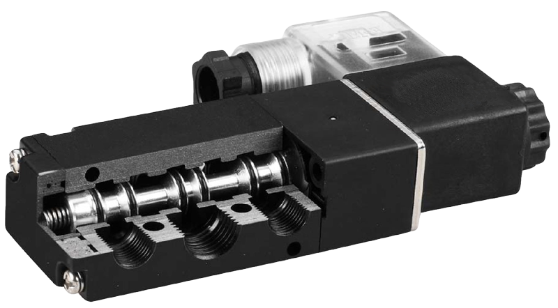
Figure 2: Sectional view of a 5/2-way solenoid valve
Mono-stable and bi-stable valves
- A mono-stable valve stays in its original position with a spring (which can be powered by air or electricity). When the valve is activated (like turning on a solenoid), it moves to its active state. Once the supply power is stopped, the valve goes back to its starting position. These valves are also referred to as single acting solenoid valves.
- A bi-stable valve changes position with a quick action and stays there. It doesn't go back to how it was before you activated it, even after the action stops. A bi-stable solenoid valve typically has a solenoid at each end, with each one controlling a different position. These are known as double acting solenoid valves.
Pneumatic directional control valve types
Air directional control valves are represented by two numbers. The first number shows how many ports the valve has, and the second number is the amount of states. For example, a 2/2-way valve has two ports (in/out) and two states (open/closed). A 5/2-way valve has five ports and two states. Directional valves usually have two, three, or five ports. The following sections explain the different types in detail. Read our valve symbols article for more details on the symbols for directional valves.
2/2-way valve
The simplest and most common type of valve is the 2/2-way valve. It features two ports and two positions (open and closed), which is why it's often called a shut-off valve. Primarily, these valves function as basic on/off switches in pneumatic systems, controlling the flow of air by either allowing it to pass or blocking it entirely. Their role in pneumatic systems is more focused on simple on/off control tasks rather than complex directional control, making them less common in comparison to other valve types designed for more specific pneumatic operations.
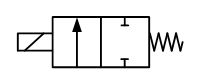
Figure 3: Circuit function of a normally closed 2/2-way solenoid valve
3/2-way valve
A 3/2-way air control valve, characterized by its three ports and two positions, plays a crucial role in pneumatic systems, especially in the operation of single-acting cylinders. This type of valve is designed to control the flow of air in a way that allows a cylinder to extend or retract and then return to its original position, ready for the next cycle. The inclusion of a third port distinguishes it from simpler 2/2-way valves, providing the essential functionality for venting the cylinder after each action. Specific applications of 3/2-way valves are:
- Single-acting cylinder control: Single-acting cylinders require air to move in one direction to extend and then need to be vented to retract. The 3/2-way valve efficiently manages this process by supplying air to extend the cylinder and then switching positions to vent the cylinder, allowing it to retract.
- Pneumatic control systems: In systems where precise control over a single action is needed, such as in automated assembly lines, packaging machines, or material handling systems, 3/2-way valves offer the necessary control and reliability.
- Actuation of pneumatic tools: Many pneumatic tools require a burst of air to operate and then need to be reset. 3/2-way valves are ideal for these applications, providing the on-demand air supply and subsequent venting.
Similar to 2/2-way valves, 3/2-way valves can be mono-stable or bi-stable. Mono-stable 3/2-way valves can be designed to be normally closed or normally open, depending on the application's requirements.
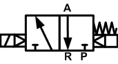
Figure 4: Circuit function of a NC 3/2-way solenoid valve
5/2-way valve
A 5/2-way valve has five ports and two states. 5/2-way pneumatic solenoid valves are versatile components used in various pneumatic systems to control the direction of airflow, thereby managing the movement of actuators, such as cylinders or pistons, in two directions (extend and retract, for example). 5/2-way valves can either be mono-stable or bi-stable.
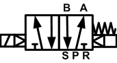
Figure 5: Circuit function of a 5/2-way solenoid valve
5/3-way valve
5/3-way pneumatic solenoid valves are advanced components in pneumatic systems, offering precise control over double-acting cylinders. Unlike simpler valves, these have a third position that allows for stopping a cylinder midway, useful for precise adjustments or pauses in movement. These valves automatically return to the middle position when not powered, ensuring safety by moving to a neutral state in power failures. Two solenoids control the movement to either extend or retract the actuator. The main types of 5/3-way valves are:
- Closed center: Blocks all ports in the middle position, saving energy and keeping the actuator's position stable without air consumption.
- Venting center: Connects ports to exhaust, allowing manual movement of the actuator. This is helpful for manual adjustments.
- Pressurized center: Keeps the actuator pressurized in the middle position, ready for quick action. This is best for systems needing fast responses.
5/3-way valves are essential in automation, material handling, packaging, and assembly lines where control over actuator positioning is critical. Their ability to precisely manage actuator movement enhances both efficiency and safety in various industrial applications.
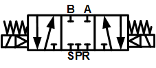
Figure 6: Circuit function of a center closed 5/3-way solenoid valve
Namur standard
Many pneumatic solenoid valves feature a standardized flange design, enabling direct mounting to devices like pneumatic actuators. A widely recognized standard for this purpose is the NAMUR standard (VDI/VDE 3845). Originating in Europe, this standard specifies a uniform interface for attaching directional control valves directly onto rotary actuators, and it has gained global acceptance. The key aspects of the NAMUR standard are:
- Global adoption: Despite its European origins, the NAMUR standard is used worldwide, ensuring compatibility and ease of integration across various industries.
- Mounting mechanism: The valves are typically secured to the actuator using M5 screws. However, in the United States, actuators are often designed with #10-24 thread patterns to accommodate local preferences.
- Sealing: To prevent leaks and ensure a secure connection between the valve and the actuator, two o-rings are used. This sealing mechanism is crucial for maintaining the efficiency and reliability of the system.
- Versatile mounting positions: The design of the interface allows for the valve to be mounted in two different positions by simply rotating it 180 degrees. This flexibility can alter the direction of the actuator's rotation based on how the control valve is energized, providing additional control and adaptability in system design.
This standardized approach simplifies the integration of solenoid valves into pneumatic systems, enhancing compatibility and ease of installation across a broad range of applications. By adhering to the NAMUR standard, manufacturers ensure that their products can be easily incorporated into systems worldwide, promoting efficiency and reliability in pneumatic operations. Figure 7 shows the dimensions for a valve with G1/4" and G1/2" ports.
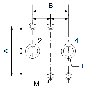
Figure 7: Schematic drawing of the Namur flange with dimensions
Table 1: NAMUR standard flange dimensional details
| T | A | B | M |
| G1/4" | 32 | 24 | M5 |
| G1/2" | 45 | 40 | M6 |
