


Burkert Type 6014 - Plunger Valve
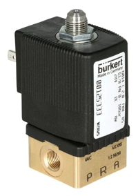
Figure 1: Burkert 3/2 way plunger solenoid valve (Type 6014)
The Burkert Type 6014 valve is a direct-acting plunger valve with a welded plunger guide tube and stopper for enhanced pressure resistance and leak prevention. It offers various seal materials for different applications. Key features include:
- Compact design with diameters up to DN 2.5.
- Secure bolted coil system to protect against vibrations.
- Banjo-threaded connection for direct mounting on pneumatic valves.
- Available in explosion-proof versions.
- Space-efficient manifold arrangement.
- Energy-saving 'kick and drop' coils for reduced power consumption.
Table of contents
- Is Burkert Type 6014 valve the right choice?
- General technical data
- Circuit functions
- Installation (Wiring)
View our online selection of Burkert 6014 valves!
Is Burkert Type 6014 valve the right choice?
The valve might be the right choice for an application if:
- The valve is used in potentially explosive atmospheres
- It's crucial to reduce the power consumption during valve operation
- The application involves tight spaces and high pressures
General technical data
Materials
- Seal: FKM (EPDM can be designed on request)
- Coil: Polyamide (Epoxy can be designed on request)
- Body: Stainless steel 1.4305/303 or brass
- Nominal diameter: DN 1.5-DN 2.5
- Circuit function: C, D, and T (discussed later)
Performance data
The duty cycle is the ratio of the time the valve can be energized (powered on) to the total time it can operate continuously without overheating. The valve assembly can be operated continuously at 100% duty cycle without any time restrictions. However, intermittent operation should not be energized for more than 60% of a 30-minute period. Additionally, there may be an option for a 5-watt coil if required for specific applications.
Operating medium
The valve is compatible with neutral gasses and other fluids such as town gas, compressed air, natural gas, hydraulic oil, water, and petrol. It is also suitable for use in technical vacuum applications.
Connection and communication
-
Port connections:
- G ⅛ and G ¼
- NPT ⅛ and NPT ¼
- Sub-base, SFB (a component that provides a mounting surface and flow paths for valve components, enabling fluid or gas regulation within the system)
- Electrical connection: DIN EN 175 301-803 form A for cable plug Type 2518
Approvals and certifications
The valve has ATEX and IECEx approvals ensuring safety in potentially explosive atmospheres.
Circuit functions
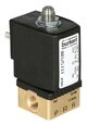
Circuit function C (CF C)
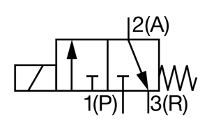
Figure 2: Circuit function C
The valve functions as a 3/2-way normally closed direct-acting solenoid valve.
Circuit function D (CF D)
Figure 3: Circuit function D
The valve functions as a 3/2-way normally open direct-acting solenoid valve.
Circuit function T (CF T)
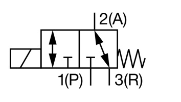
Figure 4: Circuit function T
The valve is a 3/2-way direct-acting solenoid valve (normally closed) with an optional flow direction. The valve's internal design permits fluid flow in either direction, and the installer can choose the desired orientation during installation to achieve the desired functionality.
Electrical data
The valve is designed to work with a power supply of 24 volts direct current (24 V DC). To ensure safety, the valve is used with an intermediary intrinsically safe apparatus that acts as a protective middleman between the 24 V DC power supply and the valve.
Table 1: Function values at different temperatures
| Function values for valve | At 20 𐩑C (68 𐩑F) | At 55 𐩑C (131 𐩑F) |
| Minimum switching current | 30 mA | 30 mA |
| Nominal resistance coil | 310 ohms | 360 ohms |
| Minimum terminal voltage | 9.3 V | 10.8 V |
Table 2: Maximum allowable values for the valve
| Ui (Input voltage) | 28 V |
| Ii (Input current) | 120 mA |
| Pi (Input power) | 1.1 W |
Ambient temperature |
140 𐩑F at T6 |
| 167 𐩑F at T5 | |
Installation (Wiring)
There are three valve terminals. Terminals 1 and 2 are connected to the supply, and terminal 3 acts as the ground. The label on the coil indicates the polarity of the coil (direction of current when energized).
- - switch ON +: When the switch is turned on, the coil gets energized, creating a magnetic field. In this state, the positive wire should be connected to terminal 2, and the negative wire should be connected to terminal 1 of the valve. This activates the valve, allowing fluid to flow from one port to another.
- + switch OFF - : The coil gets de-energized when the switch is turned off. In this state, the positive wire should be connected to terminal 1, and the negative wire should be connected to terminal 2 of the valve. This deactivates the valve, stopping the flow or allowing it to pass through a different port.
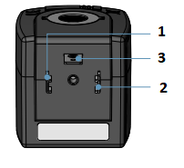
Figure 5: Valve terminals 1, 2, and 3 (protective conductor port)

