


AC to DC Transformer Guide
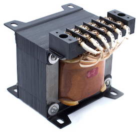
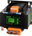
Figure 1: Transformer
An AC to DC transformer converts alternating current (AC) into direct current (DC). AC signals, which periodically change direction, are efficient for transmission; however, they are unsuitable for most electronic devices that require a steady, one-directional power supply. By combining a transformer with rectifying components, AC voltage is stepped down and converted into DC voltage for safe and reliable use. This article discusses the working principle, components, and applications of AC to DC transformers.
Table of contents
- What is an AC to DC transformer?
- Designing an AC to DC transformer
- Half-wave rectification
- Full-wave rectification
- How to choose a transformer
- Factors to consider when selecting a transformer
- Applications
- Limitations
- FAQs
View our online selection of transformers!
What is an AC to DC transformer?
A transformer is a device used to transfer electric energy from one AC circuit to another. A transformer can increase (step-up) or decrease (step down) AC voltage and use the principle of electromagnetic induction to decrease or increase AC voltage. Transformers are widely used on low-voltage devices such as doorbells to reduce the power in the circuits.
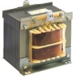
A transformer has a primary winding (Figure 2 labeled A), secondary winding (Figure 2 labeled B), and a magnetic core (Figure 2 labeled C). When AC voltage is applied to the primary winding, current passes through the winding creating a magnetic flux. The flux travels through the magnetic core and reaches the secondary winding initiating a current in the secondary side. The secondary winding can increase or reduce the voltage relative to that on the primary side, depending on the turns ratio.
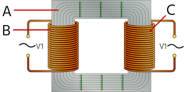
Figure 2: Transformer windings (A and B) on a magnetic core(C)
An AC to DC transformer is the transformer connected to an AC rectification circuit. A rectifying circuit converts AC voltage to DC voltage after a transformer has stepped down or stepped up AC voltage. Most devices - including cell phones and laptops - operate on direct current (DC); hence rectification circuits are vital.
Designing an AC to DC transformer
Choosing the right turns ratio is the first step towards designing an AC to DC transformer. To calculate the turns ratio, divide the number of turns on the secondary winding by the number of turns on the primary winding. The voltage ratio and turns ratio have a significant relationship.
primary turns/Secondary turns = Primary voltage/Secondary voltage
Properties of the transformer, such as size and material, must also be considered. The size and material of a transformer significantly affect the current load rating. The current load rating is the maximum current a transformer can provide at a specific temperature. The correct size and material will ensure that the transformer can convert reliable energy into a circuit. Read our transformer sizing and calculator article to know more about the current and power relations in a transformer.
The design of an AC to DC transformer is heavily dependent on the rectification circuit. The type of rectification circuit will dictate the design of an AC to DC transformer. There are two types of rectifying circuits: half-wave rectification and full-wave rectification.
Half-wave rectification
The simplest form of a rectifier is the half-wave rectifier. The construction of a half-wave rectifier is simple and has only three components: a diode, a transformer, and a resistive load. Half-wave rectifiers are used alongside transformers to produce the required DC voltage.
Half-wave rectifiers use only one diode to transform AC voltage (Figure 3 labeled A) to DC voltage at load resistor (Figure 3 labeled R). The single diode (Figure 3 labeled D) connects in series with the secondary winding of the transformer (Figure 3 labeled B).
The diode becomes forward biased (ON state) and conducts current initiating current flow through the load resistor. A diode allows the current to flow in only one direction. During the negative cycle of the input voltage, a corresponding negative voltage is induced in the secondary side, and the diode doesn’t conduct. Hence, there is no current flow through the output resistor during the negative cycle of the input voltage as the diode behaves as an open circuit. Therefore the output gives only alternate positive cycles.
Across the secondary output, often a capacitor molds the waveform to the required DC voltage. Smoothing the variable waveform is the main challenge of using half-wave rectifiers. Read our electrical transformers overview article for more information on the working of rectifier circuits.
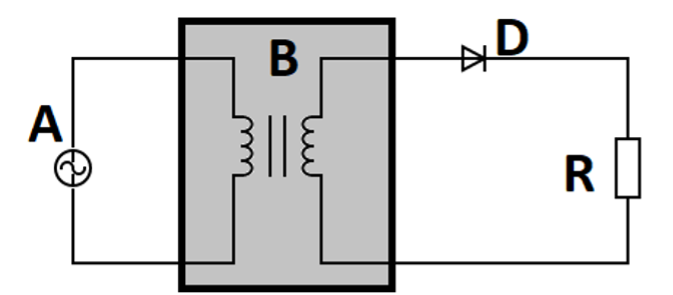
Figure 3: Basic half wave rectifier circuit: AC voltage source (A), step-down transformer (B), diode (D), and resistor (R.
Half-wave rectifiers have various applications, including the following:
- Signal demodulation: An original signal can be recovered through the demodulation process.
- Power Rectification: Half-wave rectifiers can help convert AC to DC.
- Signal peak detector: A waveform's peak value can be detected using a simple half-wave detector.
However, power loss, low voltage output, and ripples in the voltage output are common in half-wave rectifiers.
Full-wave rectification
Full-wave rectifiers are the best option for converting AC voltage to DC voltage. A full-wave rectifier converts both halves of an AC signal to a DC signal. Unlike the half-wave rectifiers, the full-wave rectifier uses multiple diodes.
Full-wave rectifiers are of two types; center-tapped full-wave rectifiers and full-wave bridge rectifiers. The center-tapped full-wave rectifier has three components - a transformer, two diodes, and resistive load. The key feature of a center-tapped rectifier is that it has a wire connected to the center of the secondary winding, as seen in figure 4. During the positive half cycle of the input waveform, diode D1 is forward biased, creating a positive cycle across the capacitive load. The capacitor is used to smooth out the pulsating output waveform. During the negative half cycle of the input waveform, diode D2 is forward biased, creating a positive cycle across the capacitive load.
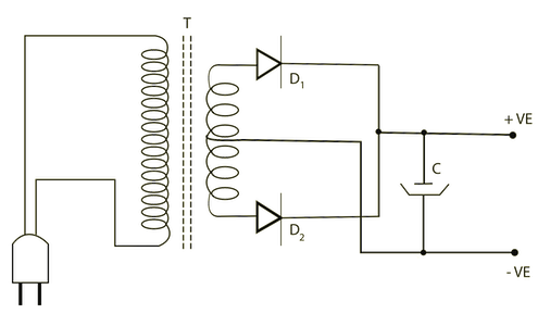
Figure 4: Center-tapped full-wave rectifier
On the other hand, full-wave bridge rectifiers have four diodes and a resistive load. During the positive half cycle of the input voltage, diodes D2 and D3 are forward biased while D1 and D4 are reverse biased (OFF state); hence diodes D2 and D3 conduct the input signal to the output. During the negative half cycle of input voltage, diodes D1 and D4 conduct, while D2 and D3 remain in the OFF state, creating an output voltage at the load. In a full-wave rectifier, the output voltage is produced during both positive and half cycles of the input voltage, unlike a half-wave rectifier. Therefore, the efficiency of a full-wave rectifier is twice that of a half-wave rectifier.
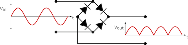
Figure 5: Full-wave bridge rectifier
Most devices use full-wave rectifiers, including phones, televisions, radios, laptops, etc. Full-wave rectifiers have an efficiency rate of 81.2%, while half-wave rectifiers only have an efficiency of 40.6%. However, the construction of full-wave rectifiers is more expensive because of the multiple diodes required.
How to choose a transformer
When choosing a transformer, evaluate factors such as load and the application. Looking deep into the design is necessary to ensure that the transformer meets your needs. Here are questions that will help you find a transformer that meets your needs.
- Does the transformer have enough capacity to handle the size of the load you expect?
- How durable is the transformer?
- Can the load capacity be increased to accommodate more load?
- Does the cost of the transformer match your budget?
Factors to consider when selecting a transformer
Safety requirements
Safety should be the topmost priority. Always check the details to ensure that the transformer cannot harm anyone. Besides, the transformer must be certified by a safety agency.
Input and output voltage
The input and output voltage determines the transformer used. The number of turns in the primary winding determines the input voltage. The output voltage depends on the turns on the secondary winding.
Mounting configurations
The common choices for mounting are the Chassis mount (installed inside industrial enclosures) and PC mount (attached to the chassis). There are also other great mounting options. Knowing the layout and method (vertical, horizontal, or flat) will help you consider mounting options.
Space limitations
Always specify the size limitations when choosing a transformer. Define the height, length, and width of the transformer needed for a particular application. The size specifications are essential in ensuring that you don't run out of space.
Applications
- In-house appliances like washing machines are used as power supply circuits.
- Devices that we use daily, like cell phone chargers, rely on AC to DC transformers for their functionality.
- Other home devices that require AC to DC transformers include refrigerators, televisions, electric cookers, etc.
- The medical sector also relies on AC to DC transformers to operate some equipment.
- The AC to DC transformers are heavily relied on in automation processes.
Limitations
Despite the many applications of AC to DC transformers, there exist challenges to using them. These include the following:
- The variation in the DC voltage output. The fluctuation in the output voltage makes it risky to connect devices directly from an AC to a DC transformer.
- AC to DC transformers waste energy by releasing a lot of heat energy. The wastage contributes to the high cost of installing and maintaining an AC to DC transformer.
- AC to DC transformers take up a lot of space.
FAQs
How to select the right transformer?
Appliances have labels containing details about the watts or amperes it needs. Check for the details of the machines.
What is meant by a step-up or step-down transformer?
Step-up transformers increase voltage, and step-down transformers decrease voltage at the secondary side relative to the primary side. The principle of electromagnetic induction is applied to step-up or step-down voltage.


