


Burkert 8611 Solenoid Valve Controller - How They Work
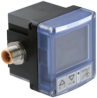
Figure 1: Burkert 8611 proportional valve controller
The Burkert 8611 process controller was engineered to abstract control theory into a versatile, easy to configure, and reliable control system. With a diverse set of inputs and outputs, the 8611 can control proportional solenoid valves and other process valve types or actuating devices. Common control applications which can be solved with the 8611 include flow rate, pressure, temperature, conductivity, pH and filling level. The 8611 uses a closed loop control system with PI or P control loops to reduce system error and accurately control a process. Due to the 8611 handling all logic for control, it can free up PLC resources in your system.
Additionally, multiple mounting styles exist to support the numerous valve styles. Figure 1 shows the Burkert 8611. To further reduce installation time and programming complexity, all Burkert proportional valves and sensors are compatible with the 8611 controller and have their values memorized. When utilizing a different brand’s proportional solenoid valve, the operating parameters need to be inputted correctly for optimal performance. We advise you to read our technical article on proportional solenoid valve controllers to further understand how pulse width modulation (PWM) and PI (proportional and integral) control theory works in the Burkert 8611 controller.
Table of contents
- Closed loop control
- How the Burkert 8611 controller works
- What can it control?
- Control functions
- Mounting options
- Software features
- Accessories
- Approvals and standards
- Controller selection criteria
- 8611 selection chart
- Integration with non-Burkert products
Buy Burkert 8611 Proportional Solenoid Valve Controller Online Now!
Closed loop control
In contrast with the 8605 controller, the 8611 controller utilizes a PI (proportional and integral) control loop, to adjust a control variable (i.e. PWM switching frequency) in relation to measured feedback provided from the process variable being controlled (i.e. pressure). The PI control loop uses parameters known as proportional and integral terms to dynamically adjust the control variable to reduce error. This is considered a closed loop system and the advantages of a closed loop control system such as a PI loop include:
- Reduced hysteresis from set point
- Automated process error correction
- Increased process stability
How the Burkert 8611 controller works
The 8611 controller is designed to control a variety of valves or other switching actuators in a closed loop system using PI control. Depending on the desired process to control, different controller inputs, outputs, and control functions will be used. The inputs will be utilized to measure process variables from sensors (flow-rate, pressure, temperature, filling level, etc.), and for set-point signal connection. The outputs will be utilized to control valves, like proportional solenoid valves, or other actuating devices. It is important to note that the control function of the system will change with respect to the desired process variable to control. Figure 2 shows the Burkert 8611 control block diagram. The operation of the 8611 is dependent on three critical parameter settings:
- Control variable: This selection defines the actual variable that will be controlled. Possible selections are flow-rate, pressure, temperature, filling level, or ratio control.
- Actuating element (manipulated variable): Selections are based off the actuator to control. It is possible to control proportional valves, process valves, or other actuators (i.e. a motor valve). Devices controlled with PWM requires the properties of the actuator to be input. This is critical for control of the system. All Burkert valves and sensors are memorized by the 8611 controller. For example, entering the specific Burkert proportional valve type will automatically populate its operating frequency and frequency limits. Manual input of actuator properties is also possible for other brand’s actuators.
- Process value input (feedback process actual value): This selection will define the variable used as feedback to the controller. Selections are limited to the selected control variable and actuating element. Possible selections are frequency, PT100 sensor, or standard voltage/current signal.
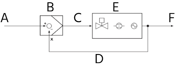
Figure 2: 8611 control block diagram: set point value (A), controller 8611 (B), manipulated variable (C), feed back process actual value (D), controlled system consisting of an actuating element, sensor, and process (E), and controlled variable (F).
What can it control?
The Burkert 8611 controller can control a wide range of products for fluid control applications. Based on the output signal, it can control normally open (NO) or normally closed (NC) process valves, proportional solenoid valves, or linear actuators as a few examples. Understanding your system needs from a controller input (sensor) and output (actuating device) perspective is crucial before selecting the needed controller model. Figure 3 shows the hardware architecture of the Type 8611. Please view our selection chart to know which inputs and outputs are available on different versions. The power supply for all versions is 24 V and can be wired with an 8 pin M12 plug connection or through a terminal input for the cabinet mount version. Input and output wiring connections vary depending on the version. Cables can be purchased separately, additionally the pin-out for all connectors is specified in the 8611 user manual. The possible outputs available and appropriate actuating devices compatible with each output are:
- Analog output, process value output: Outputs a 0 – 10 V voltage or 4 – 20 mA current signal which can be utilized by devices such as a flow rate sensor or linear actuator.
- Transistor output: Outputs a PWM signal to control proportional solenoid valves. PTM output signal is also possible with various mounting versions. The switching voltage is 24V with a maximum possible current of 1.5 A. The control frequency range is between 1.2kHz to 20 Hz.
- Binary output: Configurable transistor output between 0-24 V DC with a maximum current of 1.5 A for NO/NC process valve control.
- Electrical power supply for sensors: 24 / 5 V DC available as a power supply for sensors.
The possible inputs available for setpoint control or external sensors are:
- External setpoint input: Standard voltage (0 – 10 V) or current (4 – 20 mA) signal can be applied for set-point or ratio control. The setpoint input is often from a programmable logic control (PLC) to automate the control.
- Sensor input: The measured process value input used for error correction is from sensor inputs. Standard voltage (0 – 10 V) or current (4 – 20mA), frequency signal, and Pt 100 temperature sensor inputs are available. The flow-fitting mount version can be ordered with an integrated hall sensor. The internal hall sensor can only be used with the Burkert flow-rate fitting Type S030.
- Binary input: Utilized to enable or disable various controller functions, typically the input is taken from a safety switch or feedback from a logic controller. The logic ON voltage range is from 3 to 30 V. An input less than 3 V is considered logic OFF.
For further integration into a control system, RS485 and IO-link interfaces are available on request. RS485 and IO-link interfaces allow for read and write parameter access to the 8611 without operator access. These communication interfaces are only available with the panel mount style.
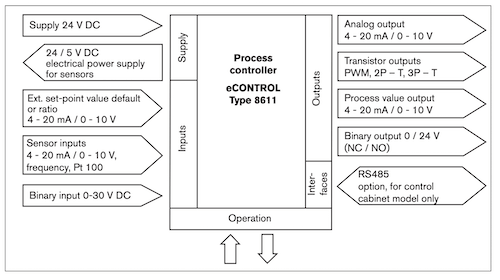
Figure 3: Type 8611 hardware architecture
Control functions
The control function is determined by the selected actuating element and will configure how the controller will regulate the process. Each control function includes parameters specific to the actuator being controlled. The configuration of each control function will be determined by the selection of the control variable. Additionally, the programming of the sensor inputs and set-point signal will be selected based off of each control function. The configuration of each controller function is guided based on the control variable to limit the possible configuration choices.
The PI parameters for each function should be tuned to improve the system control. Examples for the setting and calculation of the PI parameters can be found in the 8611 user manual. Additionally, a test mode exists to assist in tuning.
- Proportional valve continuous control: This function is used to control proportional valves with a set-point input, sensor input, and PWM output signal. The PWM frequency must be set according to the selected valve type for proper operation. The PWM frequency of all Burkert valves is memorized by the 8611 controllers. The specific type can be entered during configuration to automatically load all operating parameters.
- Process valve quasi-continuous control: This function will control a process valve without position feedback. This function is commonly used in applications where feedback is not possible due to harsh operating conditions such as high temperature, high humidity, or space limitations. A process valve is controlled with a PTM (pulse-time modulation) output and process feedback.
- Control valve continuous control: This function is used to control a valve using the analog output (4-20 mA or 0-10 V) for control. This function is commonly used with motor valves or positioners for flow rate control. A control valve can be operated using a standard 0-20 mA or 0-10 V signal and process feedback.
- Open/Close valve quasi-continuous control (2-state, 3-state): This function is used to control open/closed valves using the transistor outputs of the controller. Unlike a purely ON/OFF control scheme the time for opening and closing of the valves is varied proportionally to the set-point and actual value deviation. 2-state control is used for controlling a single control valve and 3-state control is used for controlling two separate control valves. 3-state control will utilize 2 transistor outputs. This function can operate with normally open (NO) or normally closed (NC) valves.
- Ratio control: This function is used to control flow rate with respect to an uncontrolled flow rate. The relationship between the uncontrolled flow rate and controlled flow rate is defined by a ratio factor. The controlled flow rate is adapted to the uncontrolled flow rate so that it corresponds to a specific ratio. This function is commonly used in fluid mixing applications. The Burkert Type S030 flow-rate fitting used on the fitting mount 8611 can be used to measure the flow-rate.
Mounting options
The Type 8611 features five mounting styles. The five styles are: fitting, wall, rail, proportional valve, and panel. The wall and rail mounting configurations will be discussed together, as the main difference is an adapter plate for mounting. Input and output connections may vary depending on the mounting style. Therefore, typically the input/outputs required for an application are known and decided first to then choose between the available mounting style that has them.
Fitting mounting
The controller is mounted to the Burkert S030 inline flow sensor fitting, typically on a pipeline system as seen in Figure 4. The S030 measures flow rate using a built-in paddle wheel. As fluid flows through the pipe, the paddle wheel rotates and produces pulses whose frequency is proportional to the flow rate. The flow rate is measured by an integrated hall-sensor. The 8611 uses the frequency as feedback for output control. The power supply, set-point and binary inputs along with the continuous signal and binary outputs can be wired with an 8-pin M12 connector. Lastly, the continuous signal and transistor outputs can be wired with a 4-pin M8 plug. There are 5 models available based on the sensor input required.
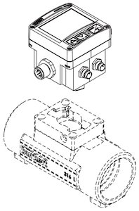
Figure 4: Inline pipe mount on a flow sensor fitting for the Burkert 8611
Proportional valve fitting
The 8611 can be directly connected to a proportional valve with a DIN 175301 - 803 Form A (shortly DIN-A) plug connection, as seen in Figure 5. This model includes a female plug at the rear of the process controller. By utilizing the DIN-A mounting point, the transistor output to control the valve is already connected. No extra wires or connections are needed. Sensor inputs are wired with a 3-pin M8 connector. The power supply, set-point, and binary inputs along with the continuous signal and binary outputs can be wired with an 8-pin M12 connector. There are three models available based on the sensor input required (each type can only accept one sensor type).
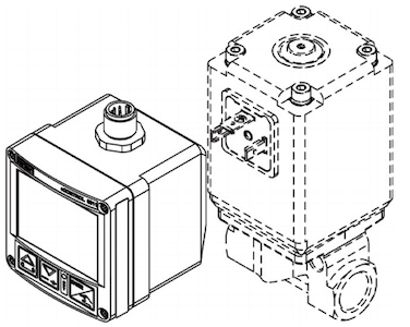
Figure 5: Proportional valve direct mount for the Burkert 8611
Wall & rail assembly
Wall & rail assembly models have adapters to mount directly to a DIN rail or fastened to a wall, as seen in Figure 6. Each model has separate adapters and are included with the 8611 controller. The power supply and sensor inputs are available through a 3-pin M8 plug located on the bottom of the controller. The power supply, set-point, and binary inputs along with the continuous signal and binary outputs can be wired with an 8-pin M12 connector. The continuous signal and transistor outputs wired to with a 4-pin M8 connector. There are 4 models for wall assembly and 3 models for rail assembly available based on the sensor input required.
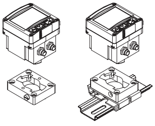
Figure 6: Wall assembly (left) and rail assembly (right) by utilizing an adapter plate for the Burkert 8611
Panel mounting
The panel mount style uses fastening elements to mount directly to a control panel cut-out, as seen in Figure 7. Fastening elements are included with the 8611. All possible sensor inputs are available. Inputs and outputs are accessed from terminal blocks located at the rear of the controller. Terminal blocks consist of spring terminals for wiring. There is only one model available for panel mounting, see our selection chart for a clear layout of the available inputs and outputs.
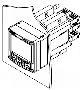
Figure 7: Panel mount for the Burkert 8611
Software features
The software features available in the 8611 help to fine tune controller performance and improve user experience by reducing setup and troubleshooting time. The main software features are discussed below.
Adjustable control parameters
The controller parameters can be used to fine tune the operation of each control function beyond its standard configuration of the tuning proportional parameters. The dynamic performance of the controller can be further improved using special control parameters. The most important parameters are listed below. All control parameters such as the proportional and integral tuning parameters can be referenced in the 8611 user manual.
- Dead zone: This dead zone causes the controller to only react to set-points in a given range. This is used to eliminate the effects of noise on a control signal.
- Zero point shut-off: The zero point shut-off is used to ensure the valve is closed tightly. If the control voltage does not reach absolute zero (i.e. 0 V), the valve may have remained open. If this parameter is activated, power to the valve will automatically be shut-off when the set-point is 2% of the total range is reached. For example, for a 0 – 10 V signal, the power output to the valve will be shut off at 0.2 V.
- Start position of control: The start position of control is only used for continuous control modes. This parameter is used to increase valve response time by immediately starting control at the “working-point of the valve.
Control tuning test mode
This can be used to determine how a process responds to a programming configuration over a defined operating control range. For example, if pressure is the process variable to be controlled it can be monitored over a specified set-point range (i.e. 0 – 10 V). This feature allows for easy fine tuning of the PI loop.
Sensor input and output calibration
The recalibration of analog inputs and outputs for service or troubleshooting is possible using the calibration mode. Calibration mode allows actual input readings to be modified. The actual display readings should only be compared against calibrated devices.
Signal scaling and filtering
The set-point input, sensor input, and analog output can be scaled to a factor before the controller processes or outputs the signal. This feature is used to match signaling between two separate devices for compatibility. This allows the controller to correctly process the input or output signal across its full range of operation. For example, the operating range of a 0 – 8V sensor can be defined so the controller processes 8V as 100% of the input signal. Filtering can be used to smoothen out an analog input or output signal. Filtering can help eliminate the effects of a noisy signal.
Unit selection
The measuring units and the number of decimal places of displayed variables can be modified to satisfy user preference.
Password protection
Access to the configuration parameters can be protected by code. The prevents unauthorized access to the controller parameter code. By default, password protection is not activated.
Accessories
Electrical connection accessories
Cables with M12 and M8 connectors are available for easy connection to power supply, inputs, and outputs.
Mounting accessories
Spare wall-mount and rail mount adaptors are available for the wall-mount and rail mount 8611 controllers. Spare mounting brackets for the cabinet mount 8611 controllers are also available.
Approvals and standards
This controller is available with the below listed approvals and standards:
- CE: Conforms to the EMC Directive EN61326
- IP65
Controller selection criteria
Determining the correct controller for your application depends heavily on the process you are trying to control. The following considerations should be taken when selecting a controller:
-
Control Type
- Determine if your application requires an open loop or closed loop controller. How stable is the system your valve is controlling? How will error affect the process? An open loop controller such as the Burkert 8605 is suitable for stable systems which operate consistently around a set-point. A closed loop controller such as the Burkert 8611 is suitable for applications that require automatic changes. These applications tend to be unstable and require error regulation.
-
Control Inputs
- The set-point signal should be compatible with the controller.
- Closed loop systems using the Burkert 8611 require sensor input to measure system error. A sensor that meets the signal requirements of the controller should be used.
-
Control Outputs
- Ensure that controller has the proper outputs to control the connector valve. The Burkert 8605 can only control proportional valves. The Burkert 8611 is a universal controller and can control proportional valves, process valves, and more. The control signal must also be compatible with the valve input.
-
Mounting Style
- There are different mounting options for each controller type. Ensure that the controller can be properly mounted and the inputs and outputs are sufficient for the sensors and valves used in your system.
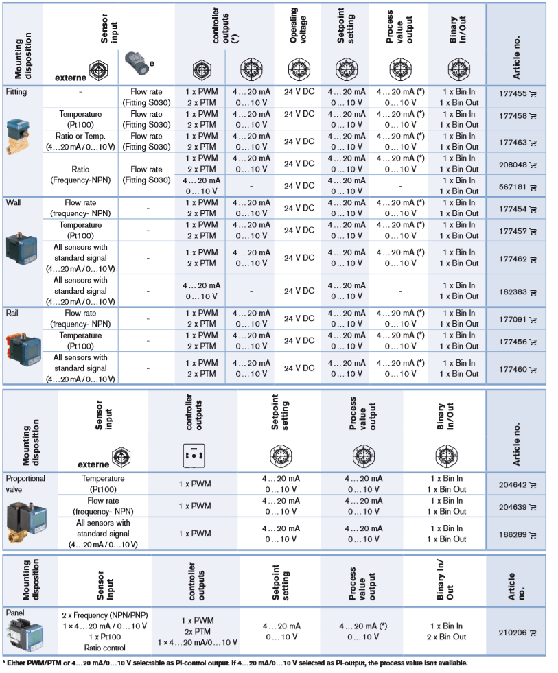
8611 selection chart
Integration with non-Burkert products
The 8611 controllers are designed and tested with Burkert products. They can be used with other brand’s components, but parameters must be manually entered in and tuned. To ensure proper performance third-party devices and components should be authorized by Burkert before using.