


Safety Valve Types and Working Principle

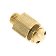
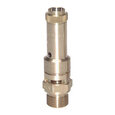
Figure 1: Safety valve
A safety valve protects a system against overpressure. Overpressure occurs when the system's pressure exceeds the Maximum Allowable Working Pressure (MWAP) or the pressure for which the system is designed. Safety valves can open very quickly compared to relief valves. A safety valve opens from a set pressure; the valve first opens a little, then opens fully so that the unwanted pressure is removed from the system as quickly as possible.
Safety valves prevent pressure increases that lead to malfunctions, fire hazards, or explosions. The system's media fully actuates a safety valve, keeping it working in a power failure. Safety valves only have mechanical parts, which operate when electronic or pneumatic safety devices fail.
Table of contents
- Important terminology
- Safety valve types
- Safety valve actuation types
- Selection criteria
- Applications
- Safety valve symbol
- Safety valve certifications
- Pressure safety valve vs relief valve
- FAQs
View our online selection of safety valves!
Important terminology
- Overpressure: Excess pressure over the set pressure of the safety valve.
- Operating pressure: The pressure at which the system works under normal operating conditions.
- Set pressure: The pressure at which the safety valve's disc begins to lift and open.
- Lift: The distance the disc moves from the closed position to the position required for discharge.
- Backpressure: The pressure built upon the safety valve outlet during flow. Backpressure = Built-up backpressure + Superimposed backpressure.
- Built-up backpressure: The pressure at the outlet when the safety valve opens.
- Superimposed backpressure: The pressure at the outlet of a closed safety valve.
- Maximum allowable working pressure (MAWP): The maximum allowable pressure at a designated temperature under normal operating conditions. MAWP is the maximum pressure that the system's weakest component can handle.
- Blowdown: The difference between the pressure at which the disc lifts and the pressure at which the valve closes. Blowdown is generally expressed as a percentage.
- Blow-off capacity: The rate at which the safety valve can release excess pressure.
Safety valve types
There are different safety valve types: valves with a spring-loaded mechanism, valves with balanced bellows, and pilot-operated safety valves. Each type has an advantage in a specific situation.
Spring mechanism
The most common safety valve is a spring-loaded or direct-acting safety valve. An advantage of this type is that it is available for pressure ranges from approximately 1 to 1400 bar. The mechanism consists of the following components:
- Expansion chamber: The expansion chamber (Figure 2 labeled A) increases the surface area that the system's media pushes against to open the safety valve, allowing it to open rapidly.
- Spring: The spring’s (Figure 2 labeled B) stiffness determines at which pressure the system’s media can begin to open the valve.
- Disc: The disc (Figure 2 labeled C) sits on the nozzle and moves up and down to allow or prevent flow through the safety valve.
- Nozzle ring: The nozzle ring (Figure 2 labeled D) affects the pressure at which the disc reseats. A high setting can cause the disc to reseat too late, while a low setting can lead to the disc randomly opening and closing when it should not.
- Nozzle: The nozzle (Figure 2 labeled E) controls the disc surface area that the media interacts with before the valve opens. This causes the media to work against a larger surface area when the valve opens, increasing the force acting on the disc and opening the disc rapidly.

Figure 2: Safety valve with spring mechanism: expansion chamber (A), spring (B), disc (C), nozzle ring (D), and nozzle (E).
The balance between a safety valve's spring force and the input force controls the valve's opening and closing. Inlet pressure and the disc's surface area with which the media interacts determine the input force. According to Pascal's Law, force equals the product of pressure and area. Therefore, as the area of the disc that the media interacts with increases, so does the force.
The most important characteristic of safety valves is that they quickly open entirely to reach maximum blow-off capacity in minimal time. This is possible because the valve's disc has a larger diameter than the nozzle. As soon as the inlet pressure is high enough, the disc lifts. At this moment, the disc surface at which the medium can reach becomes larger. This results in an input force much greater than the spring force, and the valve completely opens.
Special safety valve versions exist for incompressible and compressible media and gasses/vapors. Safety valves for gasses and vapors often open before the set pressure is reached and open to at least 50% lift at the response pressure (see Figure 3). Safety valves of this type have a significant disadvantage: they are very susceptible to back pressure, which can negatively affect the valve's safety.
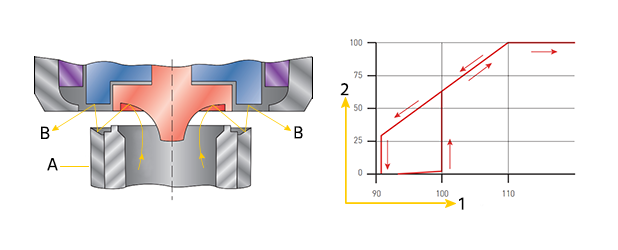
Figure 3: Safety valve mechanism for gasses and vapors (left): nozzle ring (A) and flow pattern (B). Blow-off characteristic of a safety valve for gasses and vapors (right): set pressure (1) and lift (2).
Balanced bellows

Figure 4: Safety valve with balanced bellows: guide (A), metal bellows (B), disc holder (C).
Balanced bellows safety valves are not susceptible to the negative impacts of backpressure. Bellows (Figure 4 labeled B) above the disc ensure that backpressure is evenly distributed above and below the disc. Furthermore, the spring does not encounter the media, preventing undesirable influence on the spring from the media. The downside of balanced bellows safety valves is that their MAWP is lower than direct-acting safety valves. They operate up to a maximum of 15.9 bar.
Pilot-operated safety valve
In a pilot-operated safety valve, the pressure required to open the disc is much closer to the system’s working pressure. This eliminates unnecessary pressure increases beyond the working pressure. The following components work together to make this possible:
- Pilot spring: The pilot spring (Figure 5 labeled A) controls the pressure at which the pilot poppet opens.
- Pilot valve: The pilot valve (Figure 5 labeled B) opens at a set pressure, leading to a differential that allows the main valve to open.
- Main spring: The main spring (Figure 5 labeled C) shuts the main valve until the pilot valve opens.
- Main valve: The main valve (Figure 5 labeled D) opens to allow flow from the inlet to the outlet.
- Adjusting knob: The adjusting knob on the pilot valve (Figure 5 labeled E) allows for adjustment of the set pressure.
As long as the inlet pressure is lower than the set pressure, the valve remains closed (Figure 5 left). As soon as the inlet pressure rises above the response pressure, the pilot valve moves toward the open position, allowing flow through the pilot hole and out of the valve (Figure 5 middle). This causes a pressure difference over the main valve, causing it to move upwards, allowing the remaining media to flow freely to the outlet (Figure 5 right). The valve closes when the inlet pressure drops below the response pressure again.
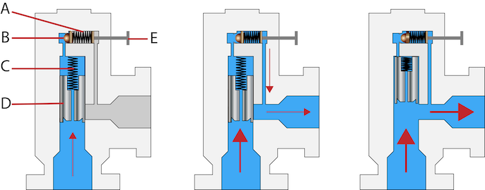
Figure 5: Pressure relief valve with guide control (left): pilot spring (A), pilot valve (B), main spring (C), main valve (D), and adjustment knob (E). The pilot valve opens in response to high enough inlet pressure, allowing flow through the pilot hole and out of the valve (middle). The main valve in the open position (right).
Dead weight safety valve
A deadweight safety valve is the simplest type of safety valve. It consists of a gunmetal valve on top of a boiler's vertical steam pipe. When pressure within the boiler rises enough, steam lifts the valve until it reduces enough to fall back into its seat. This type of valve is only suitable for stationary applications.
Safety valve actuation types
Safety valve actuation types are crucial for how a valve responds and fits into different systems. Here's a simplified overview of the three main types:
- Electric safety valves: These use electrical signals for control, making them great for systems that need precise adjustments but not necessarily fast responses. They're often used in automated setups where the valve can be programmed to react to specific conditions like pressure changes.
- Pneumatic safety valves: These valves use compressed air to work, offering quick responses. They're ideal for places where electricity isn't an option or is too dangerous. You'll find them in industries like oil and gas or chemical processing, where they help quickly relieve pressure to prevent accidents.
- Hydraulic safety valves: Operated by fluid pressure (usually oil), these valves are for heavy-duty use where you need a lot of force to open or close the valve. They provide smooth operation and are perfect for high-pressure situations where a sudden pressure drop could cause problems.
Selection criteria
To protect your system against overpressure, it is essential to understand the five selection criteria below. Please read our technical article on selecting safety valves to better understand these criteria.
- Set pressure
- Backpressure
- Discharge capacity
- Operating temperatures
- Valve and sealing material
Applications
A safety valve's purpose is primarily for industrial applications to protect against overpressure, which can cause dangerous situations such as fire or explosions. Industrial safety valves are often found in:
- Oil, gas, and petroleum industry: For example, subsurface safety valves, or downhole safety valves, are common on offshore oil wells. In the case of equipment malfunction, a safety valve can shut off rapidly to prevent oil and gas from flowing up the well in unsafe conditions.
- Energy: Safety valves in power plants are common for compressible gasses such as steam and air.
- Sanitary: Stainless steel safety valves are ideal for industries that require sanitary conditions. For example, in the food, beverage, and pharmaceutical industries.
- HVAC: Safety valves relieve pressure in the case of blocked discharge, thermal expansion, or external heat that can damage the components.
Safety valve symbol
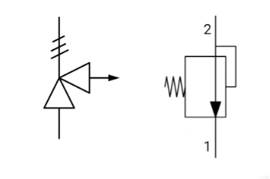
Figure 6: Varying safety valve symbols
Safety valve certifications
Safety valves must comply with various national and international standards for safety and quality. To ensure that the product complies, please consult local standards.
TÜV
The TÜV certification assesses a product's safety. It verifies that it meets the minimum requirements under the Pressure Equipment Directive (PED) 2014/68/EU. The PED outlines the standards for designing and manufacturing pressure equipment such as pressure relief devices, steam boilers, pipelines, and pressure vessels operating at a maximum allowable pressure greater than 0.5 bar.
ASME
The ASME (American Society of Mechanical Engineers) ensures the specification and accreditation of pressure vessels, boilers, and pressure relief devices.
ISO 4126
The ISO 4126 standard is a general specification for pressure relief valves, regardless of the application’s media.
Pressure safety valve vs relief valve
Pressure safety valves and relief valves have important similarities and differences.
- Similarities: Both valves types are safety devices designed to automatically open at a set pressure level to prevent overpressure in a system.
- Differences: Pressure safety valves are designed to open rapidly and quickly relieve pressure. Pressure relief valves open more gradually to control the system's pressure decrease.
Learn more in our comprehensive pressure safety and relief valve comparison article.
FAQs
What does a safety valve do?
A safety valve rapidly reduces a system's pressure when it rises to unsafe levels. The safety valve continues operating until system pressure returns to safe levels.
What is the difference between a relief valve and a safety valve?
A relief valve will not immediately halt the operation of downstream components, whereas a safety valve will.
What are the types of safety valves?
Common safety valve types are direct-acting, pilot-operated, and balanced bellows.
What is an ASME safety valve?
An ASME safety valve meets the requirements of the ASME pressure vessel code’s Section I. These valves must have a large constant flow rate at no more than 10% overpressure.