


ISO 5211 For Valves
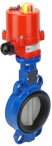
Figure 1: ISO 5211 butterfly valve
ISO 5211 is an international standard that specifies the flange dimensions, driving component dimensions, and torque reference values for part-turn actuators that connect to industrial valves like butterfly and ball valves. The standard also defines the different types of drive inserts used for these actuators. This article concentrates primarily on ISO 5211 standard and the other relevant ISO standards used for ball valves and butterfly valves.
Table of contents
- ISO 5211 standard
- Flange dimensions
- Drive inserts
- ISO 5211 torque chart
- Designation
- Other ISO standards for butterfly valves
- Other ISO standards for ball valves
Check out our selection of electric and pneumatic valve actuators
ISO 5211 standard
Modern valve designs are compliant with an ISO mounting interface. The actuator can be mounted directly to the valve without a bracket and drive log, thus saving time, hassle, and money. The highlight of following a standard like ISO 5211 is that the user can buy the parts from any manufacturer and then mix and match the valve and actuator and replace a single part if needed.
ISO 5211 is an international standard that specifies requirements for the attachment of part-turn actuators (with or without gearboxes) to industrial valves. ISO 5211 specifies the following parameters:
- The flange dimensions necessary for attaching part-turn actuators to industrial valves or intermediate supports.
- The driving component dimensions of part-turn actuators necessary to attach them to the driven components.
- The reference values of torques for interfaces and couplings.
Flange dimensions
Flanges for part-turn actuators (Figure 2 labeled 1) comply with the dimensions shown in Figure 2 and Table 1. The flanges can be attached by screws, studs, or bolts. Holes for the studs, screws, or bolts are equally spaced apart and positioned off-center (see Figure 3 and Table 3), and conform to the requirements of ISO 273. ISO 273 specifies the clearance hole diameters for general purpose applications. These values are from bearing area calculations connected to ISO bolt and nut product standards.
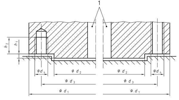
Figure 2: Flange dimensions of a part-turn actuator
Table 1: Flange dimensions (in mm)
| Flange type | d1 | d2 | d3 | d4 | h1max | h2min | No. of bolts/studs |
| F03 | 46 | 25 | 36 | M5 | 3 | 8 | 4 |
| F04 | 54 | 30 | 42 | M5 | 3 | 8 | 4 |
| F05 | 65 | 35 | 50 | M6 | 3 | 9 | 4 |
| F07 | 90 | 55 | 70 | M8 | 3 | 12 | 4 |
| F10 | 125 | 70 | 102 | M10 | 3 | 15 | 4 |
| F12 | 150 | 85 | 125 | M12 | 3 | 18 | 4 |
| F14 | 175 | 100 | 140 | M16 | 4 | 24 | 4 |
| F16 | 210 | 130 | 165 | M20 | 5 | 30 | 4 |
| F25 | 300 | 200 | 254 | M16 | 5 | 24 | 8 |
| F30 | 350 | 230 | 298 | M20 | 5 | 30 | 8 |
| F35 | 415 | 260 | 356 | M30 | 5 | 45 | 8 |
| F40 | 475 | 300 | 406 | M36 | 8 | 54 | 8 |
| F48 | 560 | 370 | 483 | M36 | 8 | 54 | 12 |
| F60 | 686 | 470 | 603 | M36 | 8 | 54 | 20 |
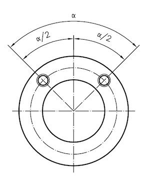
Figure 3: Positions of holes
Table 2: Position of holes
| Flange type | ⍺/2 |
| F03 to F16 | 45° |
| F25 to F40 | 22.5° |
| F48 | 15° |
| F60 | 9° |
Drive inserts
Drive inserts allow the actuators to directly mount to the valve in accordance with ISO 5211. Direct mounting eliminates the need for a coupling-type mounting kit and significantly cuts the valve/actuator assembly cost. ISO 5211 covers parallel and diagonal square drives, flat head drives, and single and two key drives. These drive inserts are on factory-built actuators or come as separate units. Also, these inserts are easily replaceable at the distributor or end-user level.
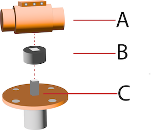
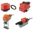
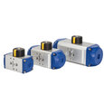
Figure 4: Drive inserts for connecting ISO 5211 actuator to butterfly valves: actuator (A), drive insert (B), butterfly valve (C)
ISO 5211 torque chart
As per the ISO 5211 standard, the maximum torque transmitted through the mounting flange of a butterfly or ball valve should comply with the values listed in Table 3. The values specified in Table 3 are based on bolts in tension at a stress of 290 MPa and a coefficient of friction between the mounting interface of 0.2. Any variation in these defined parameters can lead to variations in the values of torque transmitted. Hence, while selecting a flange type for a particular application, the additional torque that inertia or other factors may generate should be considered.
Table 3: Maximum flange torque values as per ISO 5211 standard
| Flange type | Maximum flange torque (in Nm) |
| F03 | 32 |
| F04 | 63 |
| F05 | 125 |
| F07 | 250 |
| F10 | 500 |
| F12 | 1000 |
| F14 | 2000 |
| F16 | 4000 |
| F25 | 8000 |
| F30 | 16000 |
| F35 | 32000 |
| F40 | 63000 |
| F48 | 125000 |
| F60 | 250000 |
| F80 | 500000 |
| F100 | 1000000 |
Designation
Part-turn valve actuators that comply with ISO 5211 standard can be designated as shown in Table 4.
Table 4: ISO 5211 valve designation
| Flange designation | Spigot identification | Drive identification | Drive dimensions (in mm) |
| Flange types given in Table 1 |
Y: with spigot
N: without spigot |
V: Single key drive
W: Two key drive L: Parallel square drive D: Diagonal square drive H: Flat head drive |
The actual dimensions of the drive in mm |
Example
Consider a part-turn actuator with the following designation:
EN 150 5211 - F07 - Y - V - 22
The designation can be decoded as follows:
- F07: Flange type
- Y: With spigot
- V: Single key drive
- 22: 22 mm drive diameter
Therefore, EN 150 5211 - F07 - Y - V - 22 identifies a part-turn actuator attachment in accordance with ISO 5211 standard with F07 flange type, spigot and single key drive with a 22 mm diameter. Please note that marking the designation on the actuator is not mandatory. Refer to the ISO 5211 document for more information on the dimensions of drive components for different types of drive inserts.
Additional features of ISO 5211 actuators
ISO 5211 direct-mounted valves come with additional features like a blow-out proof stem design, handles with an inherent locking device, or an anti-static design. In a ball valve, an anti-static design eliminates the static charge generated on the ball due to friction. The design protects the valve against sparks that can ignite the fuel flowing through the valve. ISO 5211 actuator options for modulation DPS (Digital Positioning System) or fail-safe BSR (Battery Safety Return) are also available.
Other ISO standards for butterfly valves
ISO 5752
ISO 5752 standard for butterfly valves specifies the basic series of face-to-face and center-to-face dimensions for two-way metal butterfly valves. Each basic series applies to flanges of mating dimensions conforming to the equivalent EN or ASME flange series.
The face-to-face dimension is the distance between the two gasket contact surfaces. (Figure 5 left side). The center-to-face dimension is the distance between the plane at the extremity of either body end port and perpendicular to its axis and the other body end port axis (Figure 5 right side).
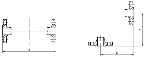
Figure 5: Face-to-face dimension of butterfly valve denoted by ‘a’ and center-to-face dimension denoted by ‘b.’
ISO 10631
ISO 10631 specifies the general requirements for design, materials (e.g., steel, cast iron, ductile iron, copper alloy), pressure/temperature ratings, and testing for butterfly valves having metallic bodies for use in flanged or butt-welding piping systems.
IS0 16136
ISO 16136 specifies the requirements for the design, functional characteristics, and manufacture of butterfly valves made of thermoplastic materials intended for isolating and control service, their connection to the pipe system, the body materials, and their pressure/temperature rating between − 40 °C and + 120 °C, for a lifetime of 25 years, and also specifies their tests after manufacturing.
Other ISO standards for ball valves
ISO 7121
ISO 7121 specifies the requirements for a series of steel ball valves suitable for general-purpose industrial applications. The standard covers ball valves of nominal sizes and is applicable to Class 50, 300, 600, 800, and 900 pressure designations. It includes provisions for ball valve characteristics as follows:
- flanged and butt-welded ends in sizes 15 ≤ DN ≤ 600 (1/2 ≤ NPS ≤ 24)
- socket welding ends in sizes 8 ≤ DN ≤ 100 (1/4 ≤ NPS ≤ 4)
- threaded ends in sizes 8 ≤ DN ≤ 50 (1/4 ≤ NPS ≤ 2)
- body seat openings designated as full bore, reduced bore, and double reduced bore
- materials
- testing and inspection.
ISO 17292
ISO 17292 specifies the requirements for a series of metal ball valves suitable for petroleum, petrochemical, natural gas plants, and related industrial applications. It includes provisions for testing and inspection and for valve characteristics as follows:
- flanged and butt-welded ends, in sizes 15 ≤ DN ≤ 600 (½ ≤ NPS ≤ 24)
- socket welding and threaded ends, in sizes 8 ≤ DN ≤ 50 (¼ ≤ NPS ≤ 2)
- body seat openings designated as a full bore, reduced bore, and double reduced bore
- materials
ISO 23826
ISO 23826 specifies the design, type, testing, marking, manufacturing tests, and examination requirements for ball valves used as:
- closures of refillable transportable gas cylinders, pressure drums and tubes
- main valves for cylinder bundles
- valves for cargo transport units [e.g. trailers, battery vehicles, multi-element gas containers (MEGCs)], which convey compressed gasses, liquefied gasses, and dissolved gasses.
However, the standard does not apply to ball valves for oxidizing gasses, toxic gasses, and acetylene for single gas cylinders, pressure drums, and tubes.