


Reducing Energy Consumption of Solenoid Valves
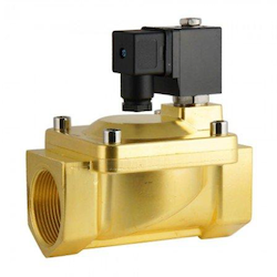
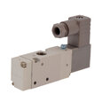
Figure 1: 2/2-way solenoid valve
Optimizing solenoid valves for energy efficiency is key to sustainable and cost-effective industrial operations. Their role in fluid flow control across numerous systems means that even small improvements in their energy use can lead to substantial overall energy savings and enhanced operational efficiency. This article discusses the various techniques for optimizing solenoid valve design and operation, highlighting the importance of energy-efficient solenoid valve innovations.
View our online selection of solenoid valves and buy one today!
Selecting the correct valve size
Selecting the optimal size for the solenoid valve is crucial for minimizing energy consumption. An oversized valve wastes energy in two ways:
- Excessive flow capacity: A valve with a flow rate exceeding process requirements allows more compressed air through than necessary. This unnecessary flow translates to wasted energy.
- Improper coil selection: Oversized valves often require larger coils to operate the valve mechanism. These larger coils consume more power, even when the valve is not actively controlling flow.
By carefully selecting a valve with the appropriate flow rate (Kv or Cv) and a corresponding coil size that matches the valve's needs, one can significantly reduce energy consumption in your system.
Design or type of solenoid valve
The energy consumption can vary significantly across different types of solenoid valves, influenced by their design and operational characteristics.
- Normally open vs normally closed: A normally open solenoid valve remains open when it is not energized, whereas a normally closed valve stays closed when not energized. Choosing a normally open valve when the operational cycle requires the valve to be closed most of the time leads to unnecessary energy waste, as solenoid valves consume energy when they are actuated. Read our normally open vs normally closed solenoid valve article for more details.
- Direct vs indirect: Direct operated valves, which control the valve mechanism directly, consume more energy but offer simplicity and reliability for high-demand applications, such as emergency shut-off systems where immediate response is critical. On the other hand, indirect operated valves are more energy-efficient, utilizing the medium's pressure through a small bleed channel to activate the valve. These are ideal for applications where energy conservation is paramount, like in HVAC systems or automated irrigation, where the pressure differential can be used to the system's advantage.
Frequency of operation and using electric ball valves
In instances where energy consumption and the frequency of operation are critical considerations, a bi-stable valve, which retains its position without continuous power supply, could be the most energy-efficient option. Latching solenoid valves, also called bi-stable solenoid valves, are energy-efficient devices that use a small permanent magnet to maintain their open or closed position, eliminating the need for continuous electrical power. Latching solenoid valves are ideal for battery-powered or mobile applications where low energy usage is crucial, offering a sustainable solution for system designs requiring minimal power consumption.
Also, electric ball valves only use energy during actuation, making them more efficient for systems with infrequent switching. However, for optimal energy savings and operational efficiency, bi-stable valves, which require no power to maintain their position, are predominantly considered.Read our electric ball valve vs solenoid valve article for more information.
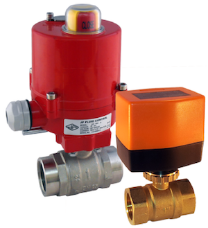
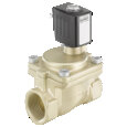
Figure 2: Electric ball valves
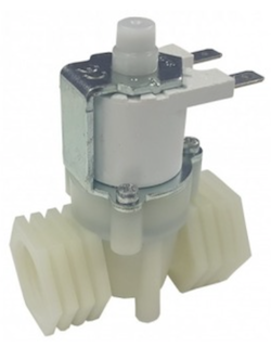
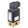
Figure 3: Latching solenoid valve
Physical parameters
By adjusting the physical characteristics of the solenoid coil, specifically by increasing the number of turns (N) and optimizing the current (I), it's possible to reduce power consumption while maintaining the necessary electromagnetic force to operate the valve. The solenoid's force is directly related to the product of the current and the number of turns (I×N).
- Increasing the number of turns: By increasing the number of turns in the coil, the magnetic field strength can be maintained or increased even with a lower current. A higher number of turns means that less current is needed to achieve the same force, leading to lower power consumption.
- Optimizing current: Adjusting the current flowing through the coil to the optimal level necessary for operation can also reduce power consumption. To adjust the current, start by consulting the valve manufacturer's specifications to understand the minimum required current. Then, experiment by gradually reducing the current while monitoring the valve's operation to ensure it remains reliable. Using a variable power supply can facilitate this process, allowing for precise control over the current. Additionally, consider implementing current-regulating devices designed for this purpose, which automatically adjust the current to optimal levels based on the operational conditions.
- Coil design: Choose coils designed for low power consumption. Some coils are specifically designed to reduce energy usage once the valve reaches its operating state.
Cycle patterns
The cycle pattern of the solenoid valve, which includes the number of times the valve opens and closes, as well as the duration it remains in each state, significantly influences its energy consumption. Selecting the correct design features, such as whether a valve is normally open or normally closed, is crucial and must align with the valve's cycle pattern within the system to ensure energy efficiency.
Example
Compare two solenoid valves based on their cycle pattern and energy consumption for an automated irrigation system that operates once a day for 30 minutes.
Step 1: Cycle pattern
Assume both valves take the same time to open and close, and they operate once daily for 30 minutes.
| Cycle pattern overview | Time (hrs) |
| Amount of time to open | 0.0033 hrs (20 seconds) |
| Amount of time to close | 0.0033 hrs (20 seconds) |
| Time in open position | 0.5 hrs (30 minutes) |
| Time in closed position | 23.4934 hrs (Remaining time in a day) |
Step 2: Energy consumption
Consider both valves have the following energy consumption characteristics:
| Valve type | Energy to open (Wh) | Energy to close (Wh) | Energy in open position (Wh) | Energy in closed position (Wh) |
| Valve A | 0.05 | 0.05 | 0.1 | 0 |
| Valve B | 0.03 | 0.03 | 0.06 | 0 |
To find the total daily energy consumption for each valve, calculate the energy for each operation phase.
-
Valve A:
- Opening: 0.05 Wh
- Closing: 0.05 Wh
- Open position: 0.1 Wh
- Closed position: 0 Wh (not consuming energy)
- Total daily consumption: 0.2 Wh
-
Valve B:
- Opening: 0.03 Wh
- Closing: 0.03 Wh
- Open position: 0.06 Wh
- Closed position: 0 Wh (not consuming energy)
- Total daily consumption: 0.12 Wh
Conclusion
Based on the comparison, Valve B is more energy-efficient for this specific cycle pattern. Also, consider other factors such as cost, maintenance requirements, and system complexity to make an informed decision on the most suitable solenoid valve for the needs.
Peak currents during opening
The power to open the valve (initial power) is much higher than the power to keep it open (holding power), with holding power being 20-40% of the initial power.
AC-powered solenoids
AC-powered solenoid valves have a peak in current at opening but lower holding current. To reduce power consumption in AC solenoid valves, consider the following methods:
Voltage drop
Lower the voltage to the coil to reduce current flow and power consumption, ensuring the solenoid still functions properly. Since the power consumed by the coil is directly proportional to the square of the current (P = I²xR, where P is power, I is current, and R is resistance), reducing the voltage leads to a reduction in current flow through the coil. This, in turn, reduces the overall power consumption.
Frequency increase
By increasing the frequency of the AC supply, the efficiency of magnetic induction in the solenoid's coil can be improved. This is because the inductive reactance (which opposes the flow of AC current in an inductor) is directly proportional to the frequency (X_L = 2πfL, where X_L is inductive reactance, f is frequency, and L is inductance). A higher frequency increases the inductive reactance, which can reduce the current and thus the power consumption, especially during the holding phase.
This method requires a compatible AC supply that can deliver the higher frequency without affecting other components or the overall system performance. Additionally, the solenoid coil and materials must be able to operate efficiently at higher frequencies without overheating or experiencing excessive electromagnetic interference.
Use double coils
This approach uses two coils in the solenoid valve: one designed for high inrush current to open the valve and another for lower holding current. Initially, both coils are activated in parallel to provide a strong magnetic field necessary for opening the valve. Once the valve is open, the system switches to using only one coil or both coils in series, significantly reducing the current and thus the power consumption. This method requires a more complex control system to switch between the parallel and series configurations. It also increases the initial cost due to the need for two coils and additional control circuitry. However, the savings in power consumption can justify these costs over the valve's operational life.
DC-powered solenoids
DC-powered valves maintain constant current, leading to higher overall electricity consumption.
The "kick and drop" design works by initially providing a high voltage to the solenoid to quickly achieve the required action (like compressing a spring) and then reduces the voltage needed to maintain the position or hold the solenoid in place. For example, if it takes 12 volts to pull in the solenoid, after the initial action is completed, the voltage can be dropped to 4 volts to keep it in position.
- Kick phase: At the start, the PWM signal is set to provide a high duty cycle, meaning the pulses are wide, and the interval between them is short. This results in a higher average voltage (or current) being supplied to the solenoid, providing the "kick" needed to quickly actuate the valve. This high power overcomes the initial resistance, inertia, and any other forces to move the solenoid from its rest position to its actuated position.
- Drop phase: Once the solenoid has actuated, the PWM duty cycle is reduced. This means the pulses become narrower, and the interval between them increases, resulting in a lower average voltage (or current) supplied to the solenoid. This "drop" in power is still sufficient to hold the solenoid in its actuated position but consumes less energy than the initial "kick" phase.
This circuitry can be integrated within the coil, in a DIN connector, or as a separate power saver module for existing systems, potentially saving up to 40% in energy.
Solenoid valves with timers
Solenoid valves with timers optimize energy use by activating the valve only during required periods, preventing unnecessary operation and energy waste.
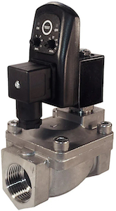
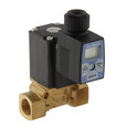
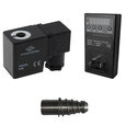
Figure 4: An analog timer installed on a solenoid valve