


What Is a Globe Valve
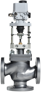
Figure 1: A pneumatic globe valve
A globe valve is a type of valve used to start, stop, and/or regulate flow in a pipeline. The valve has a movable disk-type element and a stationary ring seat within the valve body and it is effective in throttling flow and allowing for precise control. The name globe valve is from its spherical body shape. This article explores the working mechanism, features, and common applications of globe valves.
Table of contents
- Globe valve parts and working principle
- Globe valve advantages
- Globe valve disadvantages
- Applications of globe valve
- Globe valve design variations
- Globe valve flow characteristics
- How globe valves compare with other valve types
- FAQs
View our online selection of globe valves!
Globe valve parts and working principle
A globe valve has two separate chambers for flow control. The actuation process involves rotating a stem via a handwheel or mechanical actuator, which in turn, lifts or lowers the plug or disc. The globe valve working principle is explained in detail below:
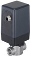
- Movement of the disc: The core mechanism of a globe valve involves the movement of a disc (or plug) (Figure 2 labeled C) in relation to the stationary ring seat. The disc is connected to a stem (Figure 2 labeled A) which is, in turn, operated by an external actuator (manual, using a handwheel, or automatic, using pneumatic, hydraulic, or electric actuators). When the handwheel or actuator is turned, it moves the stem and the attached disc in a linear motion towards or away from the seat.
- Flow regulation: In the open position, fluid flows through the space between the disc and the seat. As the valve closes, the disc moves towards the seat, gradually reducing the flow area and thereby restricting the flow. When the disc fully contacts the seat, the flow is completely stopped. This precise control over the disc position allows for excellent throttling capabilities, making the globe valve ideal for flow regulation.
- Sealing mechanism: The seat is usually designed to match the shape of the disc for a better seal. In some designs, the disc may be composed of or coated with a softer material to ensure a tighter seal.
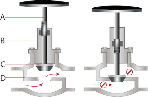
Figure 2: Globe valve diagram showing the various globe valve components: A globe valve in the open position (left), and in the closed position (right) showing stem (A), bonnet (B), disc or plug (C), and valve body (D).
Globe valve advantages
- Exceptional throttling and modulation: Globe valves are ideal for precise flow control, allowing fine adjustments to flow rate, which is crucial in systems requiring regular modulation.
- Reliable shutoff capability: They ensure a tight seal when closed, critical for stopping flow during maintenance or emergencies.
- Maintenance and repair efficiency: Designed for easy maintenance, their components are readily accessible, reducing downtime and costs.
- Versatility in maintenance: The disc and seat can be replaced or resurfaced, prolonging valve life and ensuring efficient operation.
Globe valve disadvantages
- Significant head loss: One major disadvantage of globe valves is the pressure drop due to the fluid's path through the valve, which can be mitigated by using Y-shaped or angle globe valves for less turbulence and pressure loss. The head loss should be considered while designing globe valve flow parameters.
- Increased operating force: More force is required to operate globe valves, especially in high-pressure settings, often necessitating automated actuators.
- Slower operation: Their design is not suited for situations requiring quick opening or closing due to the multi-turn operation.
- Susceptibility to cavitation and flashing: High-pressure differentials can cause cavitation and flashing, potentially damaging the valve.
- Cost: The complex design and manufacturing process make globe valves more expensive compared to other valve types.
Applications of globe valve
Globe valves are the optimal choice for applications requiring precise flow modulation, where pressure loss is not a critical concern, including scenarios such as:
- Cooling water systems
- Fuel oil systems
- Feedwater and chemical feed systems
- Boiler and main steam vents and drains
- Turbine lube oil system
- Drain and trim applications in sprinkler systems (not as control valves in fire sprinkler systems, where pressure is at a premium)
Read our globe valve applications article for more information on the industrial applications of globe valves.
Globe valve design variations
Flow path design
Globe valves have multiple designs based on their flow path:
- T- or Z globe valve (Figure 3 left): This is the most common design for globe valves, characterized by a body that forces the flow to change direction twice, creating a path that resembles the letter "Z." This design is effective for throttling because the seat and disc configuration allows for precise control over the flow. However, this design also results in a higher pressure drop across the valve with a typical L/D coefficient of ~340.
- Angle globe valve (Figure 3 middle): As the name suggests, angle globe valves have a body designed so that the inlet and outlet ports form a 90 degree angle, resembling an elbow. This design allows the fluid to change direction only once, reducing the pressure drop compared to the T- or Z-shaped design. 90 degree globe valves are useful in applications where the piping configuration requires a change in direction, combining the functions of a valve and an elbow. These globe valves have a typical L/D coefficient of ~55.
- Y-globe valve (Figure 3 right): The Y-globe valve is a variation of the standard globe valve designed to minimize the pressure drop. In this design, the valve body and the seat are angled in a way that offers a more direct flow path (less tortuous than the Z-shaped path) while still allowing for good throttling capabilities. The "Y" shape reduces the severity of the flow direction change, resulting in lower pressure loss compared to the traditional T- or Z-shaped globe valves. These globe valves have a typical L/D coefficient of ~150.
Additionally, double-seated globe valves feature two plugs and corresponding seats, enhancing their capability to handle higher flow rates and providing a balanced design that minimizes the force required to operate the valve, making them an efficient choice for applications requiring precise flow control with minimal actuation force.
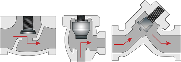
Figure 3: T- or Z globe valve (left), angle globe valve (middle), Y-globe valve (right)
Plug design
Globe valves can have one of the following plug designs:
- Plug disc: The plug disc design is characterized by its solid, tapered shape, which fits snugly into the valve seat to regulate or block flow. This type is known for its durability and effectiveness in providing a tight seal, making it suitable for applications requiring precise flow control.
- Composition disc: Featuring a disc with a replaceable insert, usually made of a softer material like rubber or PTFE, the composition disc is designed to ensure a tight seal even in the presence of particulate matter in the fluid. This type is ideal for applications where sealing against impurities is critical.
- Ball disc: As the name suggests, this disc type incorporates a spherical ball that aligns with the seat to control flow. The ball disc offers smooth operation and is particularly effective in applications requiring quick shutoff capabilities. Its design allows for easy maintenance and is suitable for moderate control applications.
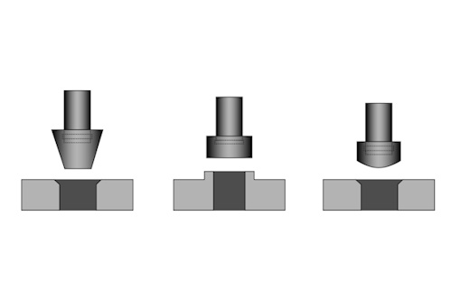
Figure 4: Globe valve disc types: Plug disc (left), composition disc (middle), and ball disc (right)
Globe valve flow characteristics
Globe valves exhibit distinct flow characteristics that are pivotal in their selection and application in fluid control systems. These characteristics are primarily defined by the valve's inherent flow coefficient (Cv), flow curve, and the relationship between the valve lift and flow rate under varying pressure conditions.
Inherent flow coefficient (Cv)
The globe valve Cv value represents the valve's flow capacity, indicating the volume of fluid that can pass through with a one psi pressure drop. Globe valve flow coefficient is typically low due to their design, which prioritizes precise flow control over high flow capacity.
Flow curves: linear vs equal percentage
- Linear flow curve: Offers a direct proportion between valve lift and flow rate, suitable for applications with constant pressure drop.
- Equal percentage flow curve: Provides an exponential relationship between valve lift and flow rate, ideal for varying pressure drop conditions, enhancing control precision.
Proper sizing is crucial to match the valve's flow characteristics with the application's requirements, ensuring efficient operation. The choice between linear and equal percentage depends on the system's pressure dynamics and control needs.
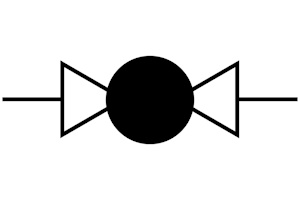
Figure 5: Globe valve P&ID symbol
How globe valves compare with other valve types
Other multi-turn/linear motion valves and quarter turn/rotary valves are common valve classifications that are comparable to a globe valve. Their purpose and function determine how they are used in different applications.
Multi-turn/linear motion valves
Industrial globe valves are multi-turn valves. A gate valve also uses a multi-turn handwheel to move the valve plug in a linear direction, but a gate valve has a straight-through flow. The valve stem on a gate valve lowers a plug or obstruction that blocks the path of flow or allows flow without requiring the medium to change direction. Consequently, gate valves have a much lower head loss (L/D=~8) when fully open, but they shouldn’t be used to regulate flow due to a drastic increase in head loss and increased wear on the gate valve’s gate and seat. Read our globe valve vs gate valve article for more details.
Quarter turn/rotary valves
A rotary valve uses a wrench handle, moving only a quarter-turn (90 degrees) to open or close the valve. The cut-off valve on a gas line is a common example of this type of valve, designed for a quick on/off function. Two common types of quarter turn/rotary valves are ball valves and butterfly valves.
- Ball valves use a sphere, or ball, with a hole bored through it, allowing flow when the hole is parallel to the direction of flow and blocking it when in a perpendicular position.
- A butterfly valve uses a thin plate to block flow when its surface is perpendicular to the direction of flow or allow flow when parallel.
Quarter turn/rotary valves have very low head loss (L/D=~3) but have limited throttling capability. Read our globe valve vs ball valve article for more details.
FAQs
How do you choose between 2 way and 3 way globe valves?
Use 2 way globe valves for on/off or throttling in a single flow path. Use 3 way valves for mixing or diverting flow between two different paths.
How do high-pressure globe valves manage to withstand high pressures?
High-pressure globe valves are designed with robust materials and thicker walls, and often feature a strengthened closure mechanism.
What is the purpose of a position indicator on a globe valve?
A position indicator visually shows the valve's open or closed status, aiding in manual checks and system monitoring.
What are the advantages of using an electric globe valve compared to a manual one?
Electric globe valves offer remote control and automation, allowing for precise flow regulation and easier integration into control systems compared to manual valves.