


The Role Of Relays In Industrial Control Systems
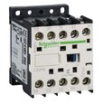
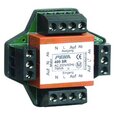
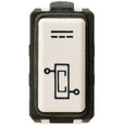
Figure 1: Electromagnetic relays for load management
A control relay is an electrically operated switch that enables current to flow through a coil that closes or opens the switch. Relays use a small current to control a larger current, making them ideal for controlling high-power devices such as motors, lights, valves, and sensors. Their versatility allows for functions such as automation, remote operation, and safety interlocks in complex systems across manufacturing, power generation, and transportation. This article explores the general wiring diagrams of 4-pin and 5-pin relays used in typical applications.
Table of contents
- What is a control relay?
- 4 and 5-pin relay
- Relay protection devices
- Control relay wiring diagram example
- Control and relay panel
- FAQs
View our online selection of relays!
What is a control relay?
A relay enables current to flow through a coil that closes or opens a switch. The coil creates a magnetic field when energized and operates a set of contacts. These contacts can then be used to switch on or off another circuit or to control a high-power device.
Advantages
- Relays provide the following advantages:
- Relays help route power to a device along the shortest path, eliminating voltage loss.
- Thinner cables can be utilized to connect the control switch to the relay; this saves space, weight, and cost.
- The same voltage and current ratings as other types of switches, such as mechanical switches, do not limit relays. This makes them ideal for switching high-power loads, such as motors and transformers.
Figure 2: Control relay symbol
4 and 5-pin relay
4-pin relays are designed to turn a single circuit on and off, while 5-pin relays are used to switch electric power between two circuits.
4-pin relay
4-pin relays have two pins (85 and 86) to operate the relay coil and two pins (30 and 87) to control a circuit. There are two types of 4-pin relays: normally open and normally closed. A normally open (NO) relay has an open contact under normal conditions/ When it closes, it turns on the power to a circuit when the relay coil is energized (Figure 3). Similarly, a normally closed (NC) relay turns off the power to a circuit when the relay coil is energized (Figure 4).
Working
Pins 85 and 86 constitute the control side. Pins 30 and 87 form the switch side. Applying power to terminals 85 and 86 energizes the relay coil. This produces a magnetic field that acts on the switch side, closing the contact from its open position in a normally open relay (or opening the contact from its closed position in a normally closed relay).
Figure 3: Normally open 4-pin relay
Figure 4: Normally closed 4-pin relay
5-pin relay
5-pin relays use two pins (labeled 85 and 86) to operate the coil and three pins (labeled 30, 87, and 87A) to switch the power between two different electric circuits. 5-pin relays have normally closed and normally open connection pins (Figure 5).
Working
Pins 85 and 86 constitute the control side. Pins 30, 87, and 87A form the switch side. The switch side has three contacts, one of them is normally closed, and the other is normally open. When the control side (pins 85 and 86) is energized by supplying power, the coil produces a magnetic field that acts on the switch side, pulling the normally closed contact to the normally open contact.
Figure 5: 5-pin relay wiring
Relay protection devices
Relays produce a large voltage spike when they are switched off. This occurs due to the rapid decay of the magnetic field in the relay coil, leading to a brief surge in voltage that can potentially damage electronic components in the circuit. Due to this, resistors or diodes are often used along with relays to manage and provide a path to dissipate the voltage spike.
Figure 6: 5-pin relays with resistor (left) and diode protection (right).
Control relay wiring diagram example
Consider a 4-pin relay system that allows the dash-mounted light switch (Figure 7 labeled A) to control a high-current load, such as a headlight or fog light (Figure 7 labeled D). The relay acts as an amplifier, allowing a small current from the light switch to control a much larger current to the load.
The system works as follows:
- When the light switch is turned on, it provides a positive voltage to pin 86 of the relay.
- This voltage energizes the relay coil, which causes the relay contacts to close.
- When the relay contacts close, they connect pin 30 of the relay to pin 87 of the relay.
- This allows current from the battery to flow through the relay to the bulb, turning it on.
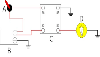
Figure 7: Dash-mounted light switch controlling a headlight using a relay: Dash-mounted light switch (A), battery (B), relay (C), and head/fog light (D)
Control and relay panel
A control and relay panel (CRP) is an enclosure that contains electrical and electronic components used to control and monitor electrical equipment. CRPs are used in various applications, including industrial automation, power distribution, and building management. CRPs typically contain the following components:
- Relays: Relays are electrical switches that are controlled by a low-power signal. They are used to switch high-power loads, such as motors and transformers.
- Contactors: Contactors are high-power relays that are used to switch high-voltage and high-current loads.
- Circuit breakers: Circuit breakers are protective devices that trip to open a circuit when a fault occurs.
- Fuses: Fuses are protective devices that melt to open a circuit when a fault occurs.
- Meters: Meters measure electrical quantities, such as voltage, current, and power.
- Indicators: Indicators provide visual and audible feedback about the status of the electrical equipment.
- Controllers: Controllers are programmable devices that control the operation of the electrical equipment.
- CRPs can be custom-designed to meet the specific requirements of an application. They can be simple or complex, depending on the needs of the application.
- Here are some examples of applications where CRPs are used:
- Industrial automation: CRPs are used to control the operation of industrial machinery and equipment, such as conveyor belts, robots, and machine tools.
- Power distribution: CRPs are used to control and monitor the flow of power in electrical distribution systems.
- Building management: CRPs are used to control and monitor building systems, such as heating, ventilation, and air conditioning (HVAC), lighting, and security.
Figure 8: Control and relay panel
FAQs
What is the difference between 4 and 5-pin relay?
4-pin relays have 4 connection pins, controlling a single circuit. 5-pin relays feature 5 pins, managing two circuits through switching contacts.
What is the difference between relay controls and communicating controls?
Relay controls use electromechanical relays for basic on/off functions. Communicating controls utilizes digital technology to exchange data, enabling advanced automation and integration in complex systems.